CAN Bus Workshop_Version 03__06-2008_EN.pdf - 第61页
1 - 35 S tudent Guide CAN BUS W orkshop Edition 0 6 /2008 2 Comm unication and Control 35 Comme nt s:
1 - 34
Student Guide CAN BUS Workshop
2 Communication and Control Edition 06/2008
34
Based on the cables connected and the position of the DIP switch, the CAN processor detects
which functions are to be controlled and at which location each assembly is.
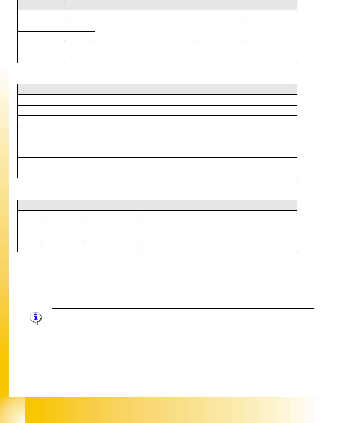
LEDs - meanings
Cable assignment at connector X1
The power connection has 2 pins for selection of the suitable CAN ID. This depends on the
position (location) of the CAN node module in the machine.
NOTE: The old nozzle changer of the C&P20 head can not be used together with the CAN node
NC tape cutter module.
The nozzle changer with new control board can also be used in machines without the CAN nodes.
DIP switch 3
1 ON: CAN ID DIP switch 2/3 – OFF: Cable select
2CAN -ID 0ON: Gantry 1
ON
OFF.Gantry 2
ON
ON: Gantry 3
OFF
OFF: Gantry 4
OFF: Cable select
3CAN - ID 1
4 ON: Tape cutter only – OFF: Nozzle changer & tape cutter
5 ON: Module in reset mode – OFF: Module in standard mode
LED Meaning
V39 Component reject bin
V45 Nozzle reject bin
V41 CPU green status LED
V43 CPU red status LED
V40 Nozzle changer 2 light barrier 24 V
V38 Nozzle changer 2 valve active
V44 Nozzle changer 1 light barrier 24 V
V42 Nozzle changer 1 valve active
Pin Signal name Signal type Comments
1 P_24V Input 24 V energy supply
2 GND - Ground
3 CANID_0 Digital input Ground (open) or 24 V (250 μA) for CAN ID
4 CANID_1 Digital input Ground (open) or 24 V (250 μA) for CAN ID