CAN Bus Workshop_Version 03__06-2008_EN.pdf - 第82页
1 - 20 S tudent Gu ide CAN BUS Wor kshop 3 CAN BU S Editio n 06/200 8 20 34 Dat u m 0 6 /20 08 Ver s io n 0 3 C A N B u s W o rk sh o p Mat hia s M ic hel SIPL ACE Cam p us A utom ati o n and Driv es 4. CAN Bus Struktur …

1 - 19
Student Guide CAN BUS Workshop
Edition 06/2008 3 CAN BUS
19
32Datum06/2008 Version 03 CAN Bus Workshop Mathias Michel
SIPLACE Campus
Automation and Drives
4. Überblick CAN Bus Struktur Siplace X
4. CAN BUS Structure Siplace X
On the Siplace X2 is
only the version 2 in the
field.
With the new stationary cameras, the vision control unit is implemented. Therefore you need an additional
CAN BUS connector for the stationary cameras. So you have new CAN Bus structure depend on the
position of cameras (Location 1, 2, 3 or 4), Head configuration and machine type.
With the SW605 there is the option WPC 4 on the X2 and X3 machine possible. This option required a new
Board on the I/O module Æ Interface 1-Wire CAN 2
X-serie
X2
X3 X4
Variant 1 Variant 2 Variant 1 Variant 2Only Vari ant 2
Variant 3
with CAN
Node
Variant 3 and
WPC 4
Variant 3 and
WPC 4
X4I
Variant 3
with CAN
Node
Variant 3
with CAN
Node
Variant 3
wi th CAN
Node
Variant 2 and
WPC 4
Variant 2 and
WPC 4
33Datum06/2008 Version 03 CAN Bus Workshop Mathias Michel
SIPLACE Campus
Automation and Drives
4. Überblick CAN Bus Struktur D-Serie
4. CAN BUS Structure D-Serie
D-serie
D1
D2 D3 (X3)
Variant 1
Variant 1
D4
Variant 1
Variant 2
Variant 3 and
WPC 4
Variant 3
with CAN
Node
Variant 2 and
WPC 4
1 - 20
Student Guide CAN BUS Workshop
3 CAN BUS Edition 06/2008
20
34Dat um06/2008 Version 03 CAN Bus Workshop Mathias Michel
SIPLACE Campus
Automation and Drives
4. CAN Bus Struktur Siplace HF aktuell
4. Current CAN BUS structure
Siplace HF
SMP BUS
C
O
M
U
n
i
t
K
S
P
3
5
4
MC
CAN Bus cable 2
Computer Unit
For each Placementarea one CAN Bus!
* with SW 505 Gantry 2 is changed to gantry 3
new cable loop!
new circuit diagram!
Trailing cable-
Interface
Gan try 1
Transport
COT 1
Tap e cutter
Control unit
CAN Bus cable 1
CAN E/
AModu
l
Sektor
4
CAN E/
A
Modu
l
Sektor
4
CAN E/
AModu
l
Sektor
4
CAN I/O
SUB Module
Section 4
Vision
Control unit
SUB Distributor Section 4
Section 4
CO T 4 / M TC
Tape cutter
Vision
Section 2
CAN I/O
Main Module
Section 2
Main Distributor Section 2
Cont ro l unit
COT 2 / MTC
Tape cutter
Axis unit
PA 2
CO T 3
Tape cutter
Trailing cable-
Interface
Gantry 3*
x6pnx11pn
Head board(C5 00 )
Gantry 1
Ter mi nator
(120 OHM)
Head board(C500 )
Gantry 3*
Te rm inator
(120 OHM)
Terminator (120 OHM)
[near the trailingcable
interface ]
Terminator (120 OHM)
[nea r the trailingcable
interface]
- CAN Bus Structure with SW 505.xx
- Com unit KSP 354
- Universal cable
(label on the cable (0301xxxx-0x)
- one CAN Bus for each placement area.
35Datum06/2008 Version 03 CAN Bus Workshop Mathias Michel
SIPLACE Campus
Automation and Drives
4. CAN Bus Struktur Siplace HF/3 Aktuell
- CAN Bus Structure with SW 505.xx
- Com unit KSP 354
- Universal cable
(Label on the cable (0301xxxx-0x)
- one CAN Bus for each placement area.
SM P BU S
C
O
M
U
n
i
t
K
S
P
3
5
4
MC
CAN Bus cab le 2
Computer U nit
Trailing cable-
Interface
Gantry 4
Transport
COT 1
Tape cutter
Control unit
CAN Bus c abl e 1
CAN E/
A
Modu
l
Se ktor
4
CAN E/
A
Modu
lSektor
4
CAN E/
A
Modu
l
Se ktor
4
CAN I/O
SUB Module
Section 4
Vision
Control unit
SUB Distributor Section 4
Section 4
COT 4
Tape cutter
Vision
Section 2
CAN I/O
Main Module
Se ction 2
Main Distributor Section 2
Control unit
COT 2 / MTC
Tape cutter
Axis unit
PA 2
COT 3
Tape cutter
Trailing cable -
Interface
Gantry 3
x6pnx11pn
He ad boa rd( C50 0 )
Gantry 1
Terminator
(120 OHM )
Head board(C500)
Gantry 3
Ter mina tor
(120 OHM)
Terminator ( 12 0 OHM)
[near the trailingcable
interface]
Axis unit
PA 1
Head board(C500)
Gantr y 4
Terminator
(120 OHM)
Trailing cabl e-
Inter face
Gantry 1
4. Current CAN BUS structure
Siplace HF 3
1 - 21
Student Guide CAN BUS Workshop
Edition 06/2008 3 CAN BUS
21
36Datum06/2008 Version 03 CAN Bus Workshop Mathias Michel
SIPLACE Campus
Automation and Drives
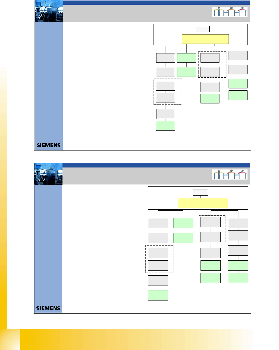
4. CAN Bus Struktur Siplace X2
4. CAN BUS structure Siplace X 2
- CAN Bus Structure with SW 605.xx
- Com unit KSP 168
- Universal cable (Label on the cable
0301xxxx-0x)
- one CAN Bus for each PA
-The stationary camera can
installed in location
1 or 3, depend on
the head configuration
-
- For new stationary cameras,
we don`t have the VCU in
sector 2 and 4. The CAN Bus
connectorisdirectlyon the
cameras.
- With this structure, the NC, sensors for the
reject boxes and the nozzle station are
controlled via CAN Bus again.
SMP BUS
Computer Unit
C
O
M
U
n
i
t
1
6
8
CAN Bus cable
PA1
X6pn
Trailing Interface
Gantry 1
Transport
Control unit
COT 1( opti onal s ta t.
Camera vers.04) /
CAN Node
(Tape cutter, NC)
CAN I/O
Sub Module
COT 4 / MTC2
CAN Node
(Tape cutter, NC)
SUB Di stributor Se c tor 4
Term inator
120 Ohm
Head board (C500)
Gantr y 1
Terminator
(120 OHM)
CAN Bus cable
PA 2
X7 p n
Main Distributor Sector 2
COT 3(optional stat.
Camera vers.04)
CAN Node
(Tape cutter, NC)
Axis unit
PA 2
(only Axes for PA 2)
CAN I /OMain
Module
COT 2 / MTC 2
CAN node
(Tape cutter, NC)
Trailing Inte rfa ce
Gantry 3
Terminator
120 Ohm
Head board (C500)
Gantry 3
Terminator
(120 OHM)
Axis unit
PA 2
(only Axes for PA1)
MC
Opti on al WPC 4
Location 4
CAN Bus 2 in PA1
Interface 1-wire CAN2
3065805 -01
Optional WPC 4
Location 2
Interfac e 1 -wire CAN2
3065805 - 01
CAN Bus 2 in PA2
37Datum06/2008 Version 03 CAN Bus Workshop Mathias Michel
SIPLACE Campus
Automation and Drives
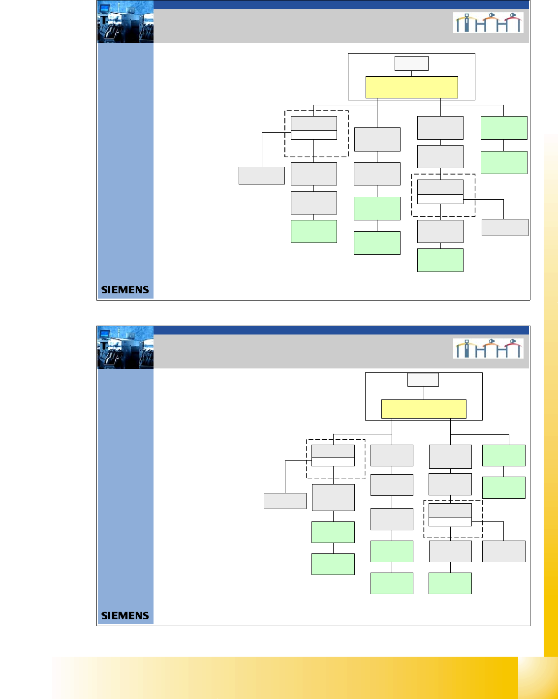
4.CAN Bus Struktur Siplace X3
4. CAN BUS structure Siplace X 3
- CAN Bus Structure with SW 605.xx
- Com unit KSP 168
- Universal cable (Label on the cable
0301xxxx-0x)
- one CAN Bus for each PA.
- For new stationary cameras,
we don`t have the VCU in
sector 2 and 4. The CAN Bus
connectorisdirectlyon the
cameras.
- The stationary camera can
installed in location 1, 4 or 3,
depend on the head
configuration .
SMP BUS
Computer Unit
C
O
M
U
n
i
t
1
6
8
CAN Bus cable
PA1
X6pn
Trailing Interface
Gantry 1
Transport
Control unit
Axi s unit
PA 1
SUB Distributor Sector 4
Tra iling Interface
Gantry 4
Head board (C500)
Gantry 4
Terminator
(120 OHM )
H ead bo ard (C500 )
Gantry 1
Terminator
(120 OH M)
CAN Bus cable
PA 2
X7pn
Main Distributor Sector 2
Axis unit
PA 2
COT 2 / MTC 2
CAN node
(Tape cutter, NC)
Terminator
120 Ohm
Trailing Interface
Gantry 3
Head board (C500)
Gantry 3
Terminator
(120 OHM)
MC
CO T 4 / MT C2
CAN node
(Tape cutter, NC)
(optional stat .
Ca mera vers.04)
COT 3 / CAN node
(Tape cutter, NC)
(optional stat .
Camera vers.04)
COT 1 / CAN Node
(Tape cutter, NC)
optional stat.
Camera vers.04)
CAN I/O
Sub Module
Interface 1-wire CAN2
3065 80 5 -0 1
CAN I/O
Main Module
Interfac e 1-wire CAN 2
30 65 805 -01
Optional WPC 4
Location 2
CAN Bus 2 in PA2
Optional WPC 4
Location 4
CAN Bus 2 in PA1