CAN Bus Workshop_Version 03__06-2008_EN.pdf - 第81页
1 - 19 S tudent Guide CAN BUS W orkshop Edition 06/20 08 3 CAN B US 19 32 Da tum06/2 0 08 Versi o n 03 CAN Bus Works hop M athias Mic hel SIPL ACE Ca mp us Automation a nd Drive s 4. Überblick C AN Bus St ru k tur Siplac…
1 - 18
Student Guide CAN BUS Workshop
3 CAN BUS Edition 06/2008
18
30Datum06/2008 Version 03 CAN Bus Workshop Mathias Michel
SIPLACE Campus
Automation and Drives
4. Überblick CAN Bus Struktur Siplace HF
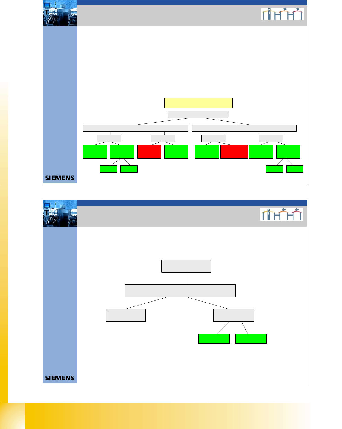
4. CAN BUS Structure Siplace HF
The HF machines will have the following differences:
- Communication unit 2x KSP 352 or one KSP 354
- HF machines with one CAN BUS for both placement areas are only supported by
station software versions 504.xx
- HF machines from station software version 505.xx only support the CAN bus structure with
one CAN bus per placement area.
- A difference is made between old and (new) universal cable harnesses.
CAN Bus Structures
HF
Universal cable harnessOld cable harness
COM KSP354COM KSP 352
SW 504 One
CAN b us per
ma chi ne
SW 505 One
CAN bus per
plac ement area
Version 01 Version 02
SW 504 One
CAN bus per
machine (was
not avail abl e)
SW 505 One
CAN bus per
placement area
COM KSP354COM KSP 352
SW 504 One
CAN bus per
ma ch in e
SW 505 One CAN
bus per placemen t
area (was not
available)
SW 505 One
CAN b us pe r
placement area
SW 504 One
CAN bus per
ma ch ine
Version 01 Version 02
31Dat um06/2008 Version 03 CAN Bus Workshop Mathias Michel
SIPLACE Campus
Automation and Drives
4. Überblick CAN Bus Struktur Siplace HF/3
4. CAN BUS Structure Siplace HF3
HF/3
COM KSP 352 COM KSP354
Universal cable harnes
Version 02Version 01

1 - 19
Student Guide CAN BUS Workshop
Edition 06/2008 3 CAN BUS
19
32Datum06/2008 Version 03 CAN Bus Workshop Mathias Michel
SIPLACE Campus
Automation and Drives
4. Überblick CAN Bus Struktur Siplace X
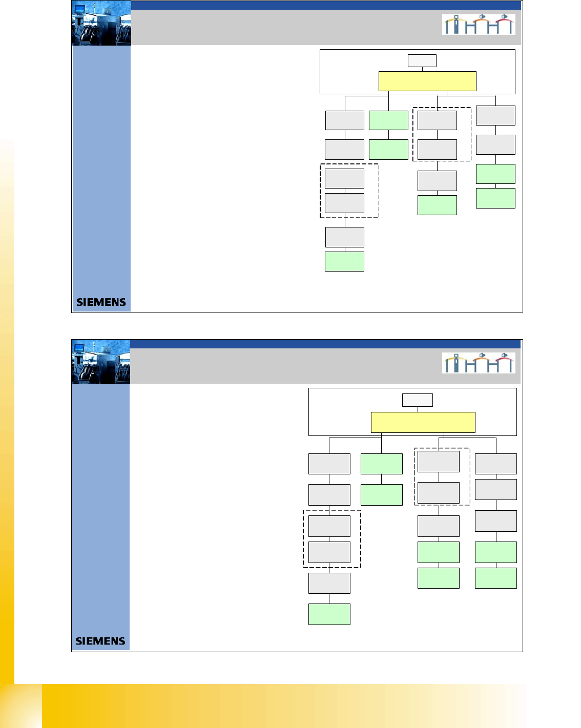
4. CAN BUS Structure Siplace X
On the Siplace X2 is
only the version 2 in the
field.
With the new stationary cameras, the vision control unit is implemented. Therefore you need an additional
CAN BUS connector for the stationary cameras. So you have new CAN Bus structure depend on the
position of cameras (Location 1, 2, 3 or 4), Head configuration and machine type.
With the SW605 there is the option WPC 4 on the X2 and X3 machine possible. This option required a new
Board on the I/O module Æ Interface 1-Wire CAN 2
X-serie
X2
X3 X4
Variant 1 Variant 2 Variant 1 Variant 2Only Vari ant 2
Variant 3
with CAN
Node
Variant 3 and
WPC 4
Variant 3 and
WPC 4
X4I
Variant 3
with CAN
Node
Variant 3
with CAN
Node
Variant 3
wi th CAN
Node
Variant 2 and
WPC 4
Variant 2 and
WPC 4
33Datum06/2008 Version 03 CAN Bus Workshop Mathias Michel
SIPLACE Campus
Automation and Drives
4. Überblick CAN Bus Struktur D-Serie
4. CAN BUS Structure D-Serie
D-serie
D1
D2 D3 (X3)
Variant 1
Variant 1
D4
Variant 1
Variant 2
Variant 3 and
WPC 4
Variant 3
with CAN
Node
Variant 2 and
WPC 4
1 - 20
Student Guide CAN BUS Workshop
3 CAN BUS Edition 06/2008
20
34Dat um06/2008 Version 03 CAN Bus Workshop Mathias Michel
SIPLACE Campus
Automation and Drives
4. CAN Bus Struktur Siplace HF aktuell
4. Current CAN BUS structure
Siplace HF
SMP BUS
C
O
M
U
n
i
t
K
S
P
3
5
4
MC
CAN Bus cable 2
Computer Unit
For each Placementarea one CAN Bus!
* with SW 505 Gantry 2 is changed to gantry 3
new cable loop!
new circuit diagram!
Trailing cable-
Interface
Gan try 1
Transport
COT 1
Tap e cutter
Control unit
CAN Bus cable 1
CAN E/
AModu
l
Sektor
4
CAN E/
A
Modu
l
Sektor
4
CAN E/
AModu
l
Sektor
4
CAN I/O
SUB Module
Section 4
Vision
Control unit
SUB Distributor Section 4
Section 4
CO T 4 / M TC
Tape cutter
Vision
Section 2
CAN I/O
Main Module
Section 2
Main Distributor Section 2
Cont ro l unit
COT 2 / MTC
Tape cutter
Axis unit
PA 2
CO T 3
Tape cutter
Trailing cable-
Interface
Gantry 3*
x6pnx11pn
Head board(C5 00 )
Gantry 1
Ter mi nator
(120 OHM)
Head board(C500 )
Gantry 3*
Te rm inator
(120 OHM)
Terminator (120 OHM)
[near the trailingcable
interface ]
Terminator (120 OHM)
[nea r the trailingcable
interface]
- CAN Bus Structure with SW 505.xx
- Com unit KSP 354
- Universal cable
(label on the cable (0301xxxx-0x)
- one CAN Bus for each placement area.
35Datum06/2008 Version 03 CAN Bus Workshop Mathias Michel
SIPLACE Campus
Automation and Drives
4. CAN Bus Struktur Siplace HF/3 Aktuell
- CAN Bus Structure with SW 505.xx
- Com unit KSP 354
- Universal cable
(Label on the cable (0301xxxx-0x)
- one CAN Bus for each placement area.
SM P BU S
C
O
M
U
n
i
t
K
S
P
3
5
4
MC
CAN Bus cab le 2
Computer U nit
Trailing cable-
Interface
Gantry 4
Transport
COT 1
Tape cutter
Control unit
CAN Bus c abl e 1
CAN E/
A
Modu
l
Se ktor
4
CAN E/
A
Modu
lSektor
4
CAN E/
A
Modu
l
Se ktor
4
CAN I/O
SUB Module
Section 4
Vision
Control unit
SUB Distributor Section 4
Section 4
COT 4
Tape cutter
Vision
Section 2
CAN I/O
Main Module
Se ction 2
Main Distributor Section 2
Control unit
COT 2 / MTC
Tape cutter
Axis unit
PA 2
COT 3
Tape cutter
Trailing cable -
Interface
Gantry 3
x6pnx11pn
He ad boa rd( C50 0 )
Gantry 1
Terminator
(120 OHM )
Head board(C500)
Gantry 3
Ter mina tor
(120 OHM)
Terminator ( 12 0 OHM)
[near the trailingcable
interface]
Axis unit
PA 1
Head board(C500)
Gantr y 4
Terminator
(120 OHM)
Trailing cabl e-
Inter face
Gantry 1
4. Current CAN BUS structure
Siplace HF 3