CAN Bus Workshop_Version 03__06-2008_EN.pdf - 第276页
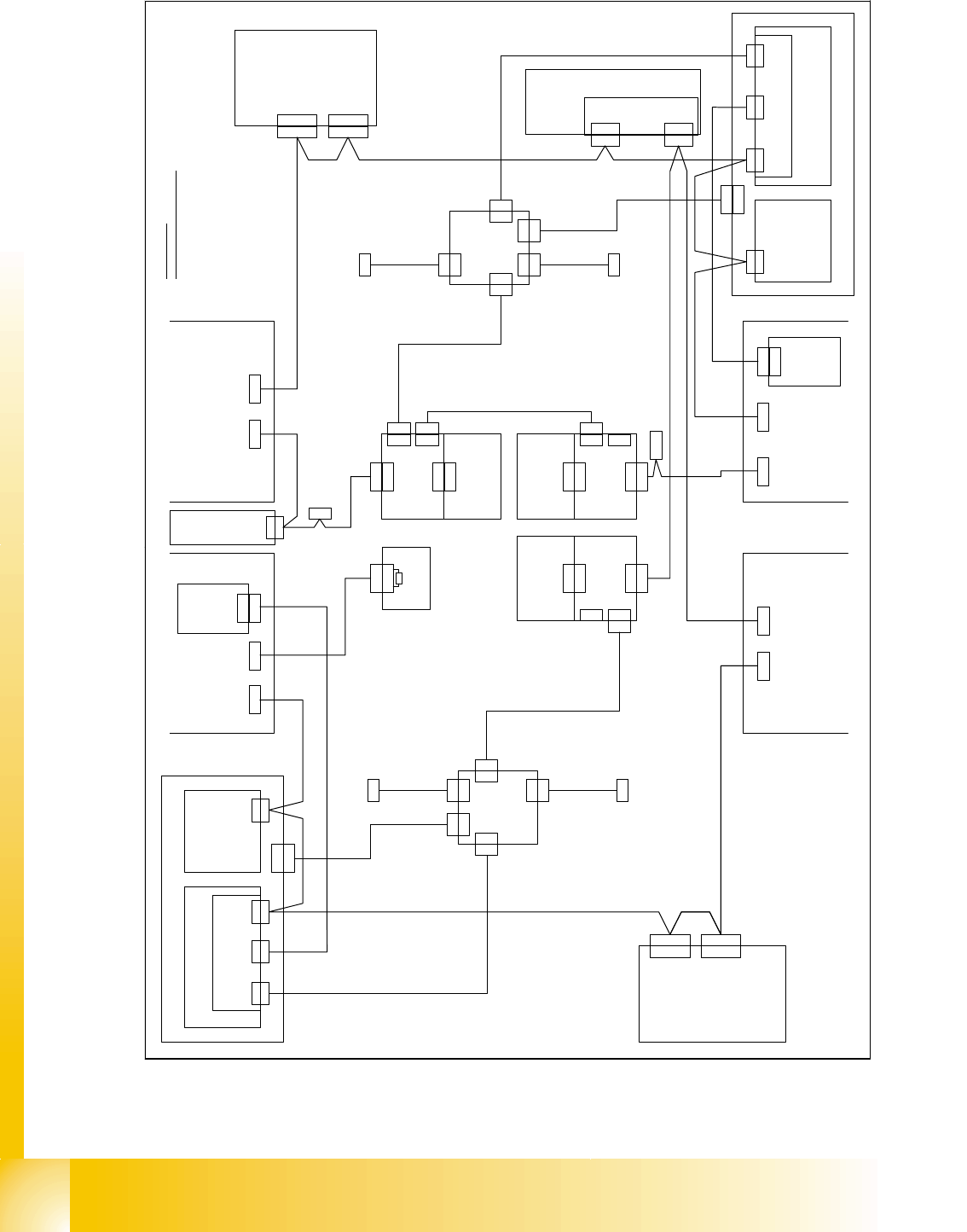
1 - 68 Siplace C AN T est Box 1 CAN T est Box Edition 04/200 8 68 Fig. 1.10 - 44 CAN bus structure X3 variant 2 with the option W PC4 V i s i o n c o n t r o l 0 0 3 6 3 9 6 1 ( q d ) C A N X 2 q d X 2 q d D o c k i n g …
1 - 67
Siplace CAN Test Box
Edition 04/2008 1 CAN Test Box
67
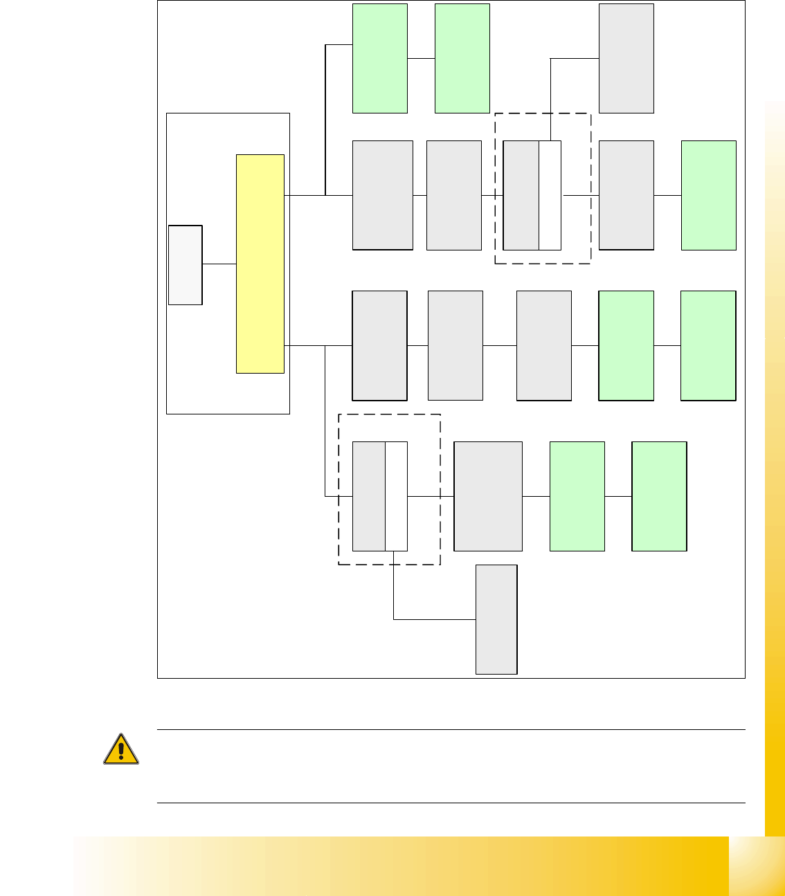
1.10.9.7 CAN Bus Siplace X3 (D3) (Variant 2 or 3) with WPC 4
The option WPC 4 is possible to install on X3 machine independent of the CAN Bus structure va-
riant 2 or 3. The precondition is a new Interface one wire CAN2, CAN Bus cable and mechanical
parts for the WPC 4 docking unit.
Fig. 1.10 - 43 CAN bus structure X3 variant 3
Attention:
For the D3 machine you have this CAN Bus structure like the X3 machine, because D3 is a X3
machine with restrictions.
SMP BUS
Computer Unit
C
O
M
U
n
i
t
1
6
8
CAN Bus cable
PA1
X6pn
Trailing Interface
Gantry 1
Transport
Control unit
Axis unit
PA 1
SUB Distributor Sector 4
Trailing Interface
Gantry 4
Head board(C500)
Gantry 4
Terminator
(120 OHM)
Head board(C500)
Gantry 1
Terminator
(120 OHM)
CAN Bus cable
PA 2
X7pn
Main Distributor Sector 2
Axis unit
PA 2
COT 2 / MTC 2
CAN node
(Tape cutter, NC)
Terminator
120 Ohm
Trailing Interface
Gantry 3
Head board(C500)
Gantry 3
Terminator
(120 OHM)
MC
COT 4 / MTC2
CAN node
(Tape cutter, NC)
(optional stat.
Camera vers.04)
COT 3 / CAN node
(Tape cutter, NC)
(optional stat.
Camera vers.04)
COT 1 / CAN Node
(Tape cutter, NC)
optional stat.
Camera vers.04)
CAN I/O
Sub Module
Interface 1-wire CAN2
3065805-01
CAN I/O
Main Module
Interface 1-wire CAN2
3065805-01
Optional WPC 4
Location 2
CAN Bus 2 in PA2
Optional WPC 4
Location 4
CAN Bus 2 in PA1
1 - 68
Siplace CAN Test Box
1 CAN Test Box Edition 04/2008
68
Fig. 1.10 - 44 CAN bus structure X3 variant 2 with the option WPC4
V i s i o n c o n t r o l
0 0 3 6 3 9 6 1 ( q d )
C A N
X 2 q d
X 2 q d
D o c k i n g u n i t 2
D o c k i n g u n i t 1
X 1 2 6
C A N W P C
C A N O U T
X 1 1 5X 1 1 6
C A N I NC A N O U T
C A N
P C B c o n t r o l
X 2 2 a o
X 2 2 a o
C A N I / O - m o d u l e 0 0 3 5 5 0 5 1 ( q b )
0 3 0 1 0 0 5 0
C A N
0 3 0 1 0 0 5 1
X 2 r d
S o
A x i s u n i t
0 3 0 5 0 3 6 5
X 3 0 _ 2 s q
C A N
D o c k i n g u n i t 3
X 1 3 6
C A N O U T
X 4 0 c a
C A N
X 2 r d
C A N
V i s i o n c o n t r o l
0 0 3 6 3 9 6 1 ( r d )
D o c k i n g u n i t 4
( c a )
C a b l e c a r r i e r i n t e r f a c e
0 3 0 1 0 6 1 2
P 3
0 3 0 1 0 0 5 4
X 1 3 5
C A N I N
X 6 8
A m b i e n t p r e s s u r e s e n s o r
P n e u m a t i c u n i t
P l a c e m e n t a r e a 2
P l a c e m e n t a r e a 1
C A N b u s w i r i n g
w i r e n o . w i r i n g S u b - D - P I N
1 " 1 - W i r e " 1
2 G N D 6
3 C A N _ L 2
4 C A N _ H 7
5 G N D 3
6 R E S E T 8
7 P o w e r F a i l 4
8 f r e e 9
9
C A N _ I N T 5
C A N
X 3 0 _ 2 s q
X 3 0 _ 1 s q
X 3 0 _ 1 s q
X 3 0 _ 2 t q X 3 0 _ 1 t q
C A N I / O m o d u l e 0 0 3 5 5 0 5 1 ( r b )
X 4 0 a a
( a a )
C a b l e c a r r i e r i n t e r f a c e
0 3 0 1 0 6 1 2
P 1
0 3 0 1 0 0 5 9
X 4 0 c a
X 4 0 b a X 4 0 a a
X 1 r b
X 1 q bX 7 q f
X 7 q f
X 1 5 q a
X 1 5 q a
C A N
X 2 q f
I n t e r f a c e 1 - W i r e C A T 5 ( q f )
0 3 0 4 1 5 7 8
M a i n d i s t r i b u t o r 0 3 0 4 6 2 2 5 ( q a )
X 5 q k
X 5 q k
0 3 0 4 1 6 2 6
P a t c h c a b l e 3 m
1 - W i r e C A T 5 D i s t r i b u t o r
0 3 0 4 0 2 1 9 ( q k )
X 3 q k
X 3 q k
X 4 q k
X 2 q k
X 2 q k
X 4 q k
X 1 q k
X 1 q k
X 1 g q
0 3 0 4 1 6 2 7
P a t c h c a b l e 3 m
0 3 0 0 9 8 2 6
P o w e r
t o 1 - w i r e h u b C A T 5
X 1 h q
0 3 0 4 1 6 2 8
P a t c h c a b l e 3 m
t o 1 - w i r e h u b C A T 5
X 5 r k
X 5 r k
1 - W i r e C A T 5 D i s t r i b u t o r
0 3 0 4 0 2 1 9 ( r k )
X 6 r f
X 6 r f
X 2 r k
X 4 r k
X 1 k q
X 2 r k
0 3 0 4 1 6 2 8
P a t c h c a b l e 3 m
X 1 5 r a
X 1 5 r a
X 1 r k
X 1 r k
0 3 0 0 9 8 3 9
X 3 r k
X 3 r k
X 4 r k
0 3 0 4 1 6 2 6
P a t c h c a b l e 3 m
X 1 2 p n X 1 1 p n
X 7 p n
C A N c a r d
X 6 p n
C A N b u s 1C A N b u s 2
P o w e r
C A N
0 3 0 4 1 5 7 8
I n t e r f a c e 1 - W i r e C A T 5 ( r f )
X 2 r f
S u b d i s t r i b u t o r 0 3 0 4 6 2 2 6 ( r a )
X 1 f q
0 3 0 4 1 6 2 7
P a t c h c a b l e 3 m
t o 1 - w i r e h u b C A T 5
t o 1 - w i r e h u b C A T 5
S o
S o
S o
S o
S o
S o
S o S o
S o
S o P i n
P i n P i nS oS o
S o
S o
M a c h i n e
c o n t r o l l e r
0 3 0 5 2 0 3 2
X 6 q f
X 6 q f
0 3 0 1 0 0 5 3
0 3 0 6 3 1 5 3
X 7 r f
X 7 r f
C A N W P C
S o
0 3 0 6 3 1 5 4
X 1 2 5 _ 2
S o
X 1 q f
X 1 2 5
C A N I N
S o
A b s c h l u s s -
w i d e r s t a n d
T e r m i n a t i n g
r e s i s t o r
0 3 0 2 7 6 4 6
X 1 4 6 X 1 4 5
X 1 4 5 _ 2
C A N I NC A N O U T
P i n
S o
X 1 r f
A b s c h l u s s -
w i d e r s t a n d
T e r m i n a t i n g
r e s i s t o r
0 3 0 2 7 6 4 6
C A N
2 / 3
X 3 0 _ 2 t q X 3 0 _ 1 t q
C A N
0 3 0 1 0 0 5 2
X 3 0 _ 1 s q
P i n
1 2 0 O h m
T e r m i n a t o r r e s i s t o r
0 3 0 2 7 6 4 6
X 1
X 1 h e
0 3 0 4 1 6 2 9
P a t c h c a b l e 3 m
0 3 0 4 1 6 2 9
P a t c h c a b l e 3 m
n . u .
X 4 0 d a
C A N
( d a )
C a b l e c a r r i e r i n t e r f a c e
0 3 0 1 0 6 2 2
P 4
X 4 h e
C A N I n
X 5 h e
X 2 h eX 1 h e
1 - W i r e C A T 5 g a n t r y
0 3 0 4 2 2 1 4 ( f e )
C A N I n
X 5 f e
X 4 f e
X 2 f e X 1 f e
X 1 f e
X 4 k e
C A N I n
X 4 0 d a
S o
X 5 k e
X 2 k e
X 1 k e X 2 k e
S w i t c h p o s . : b o t t o m
X 2 f e
1 - W i r e C A T 5 g a n t r y
0 3 0 4 2 2 1 4 ( h e )
S w i t c h p o s . : t o p
1 - W i r e C A T 5 g a n t r y
0 3 0 4 2 2 1 4 ( k e )
S w i t c h p o s .
: t o p
0 3 0 4 2 3 4 7
1 - w i r e b r i d g e
A x i s u n i t 1 / 4
0 3 0 5 0 3 6 5
1 - 69
Siplace CAN Test Box
Edition 04/2008 1 CAN Test Box
69
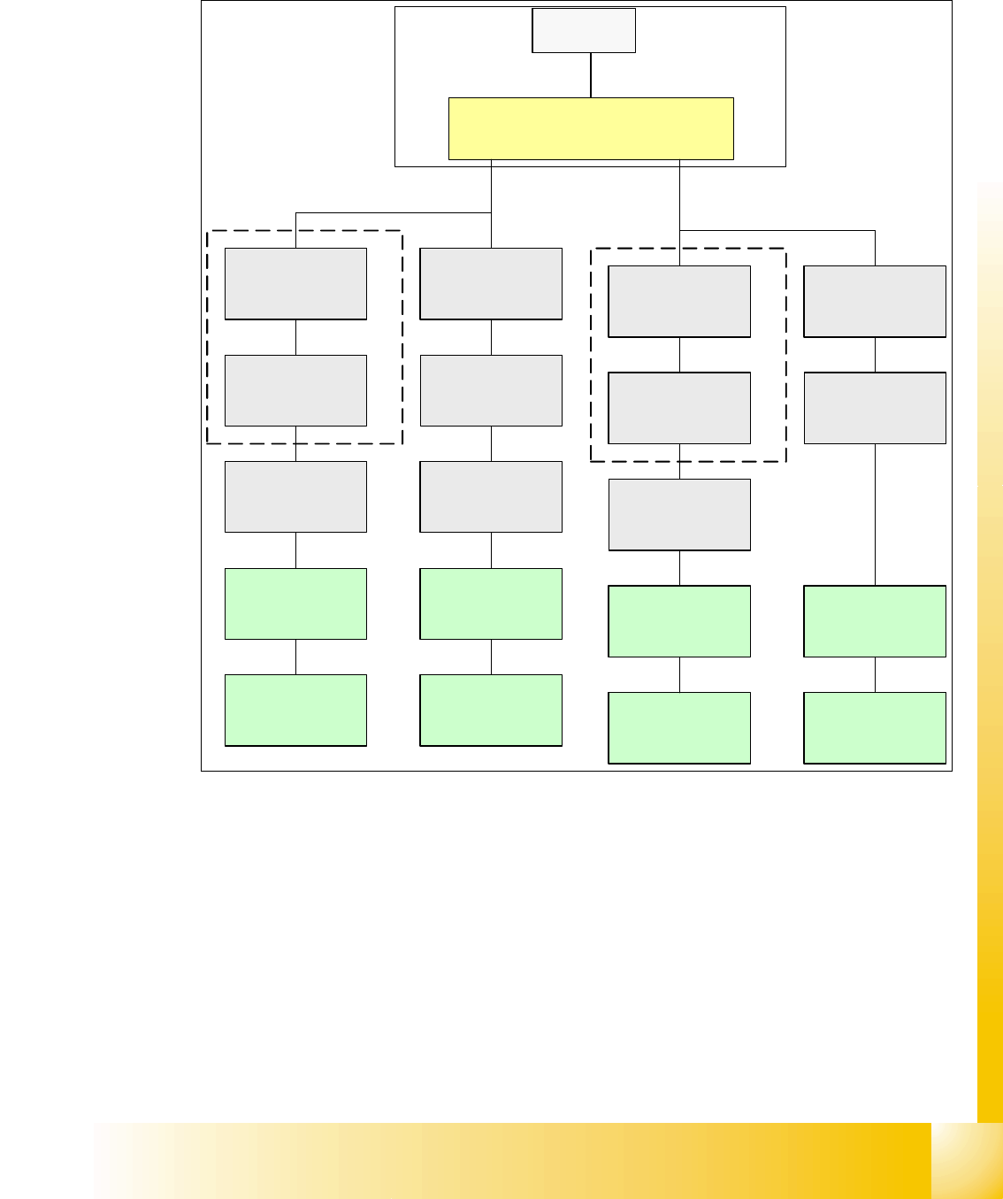
1.10.9.8 CAN Bus Siplace X4 (Variant 1)
Fig. 1.10 - 45 CAN bus structure X4 in line with operation diagram 00194418-01
SMP BUS
MC
MC
Computer Unit
C
O
M
U
n
i
t
1
6
8
CAN Bus cable
PA 1
X6pn
Trailing Interface
Gantry 1
Transport
Control unit
COT 1
Tape cutter
Axis unit
PA 1
CAN E/
A
Modu
l
CAN E/
A
Modu
l
Sektor
4
CAN E/
A
Modu
l
Sektor 4
CAN I/O
SUB Modul
Sector 4
Vision
Control unit
Sector 4
COT 4
Tape cutter
SUB Distributor Sector 4
Trailing Interface
Gantry 4
Head board(C500)
Gantry 4
Terminator
(120 OHM)
Head board(C500)
Gantry 1
Terminator
(120 OHM)
CAN Bus cable
PA 2
X7pn
Main Distributor Sector 2
COT 3
Tape cutter
Axis unit
PA 2
Vision
Control unit
Sector 2
CAN I/O
Main Modul
Sector 2
COT 2
Tape cutter
Trailing Interface
Gantry 2
Trailing Interface
Gantry 3
Head board(C500)
Gantry 2
Terminator
(120 OHM)
Head board(C500)
Gantry 3
Terminator
(120 OHM)