CAN Bus Workshop_Version 03__06-2008_EN.pdf - 第272页
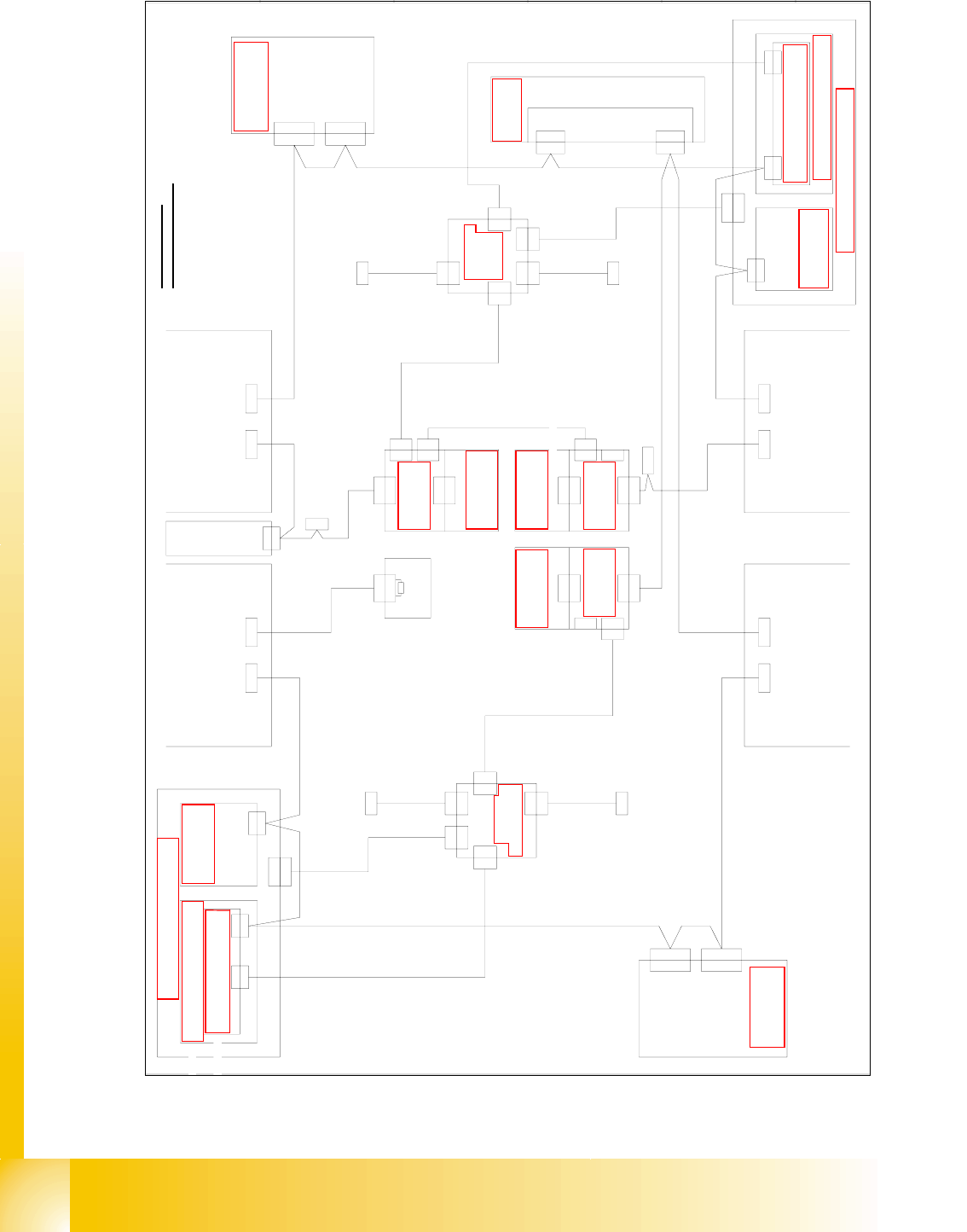
1 - 64 Siplace C AN T est Box 1 CAN T est Box Edition 04/200 8 64 Fig. 1.10 - 40 CAN bus structure X3 operation diagram 00194418-02 X30_2tq X30_1tq CAN 0301 0052 0301 0059 X6qf X6qf 0304 1626 Patchkabel 3m X5rk X5rk X3rk…
1 - 63
Siplace CAN Test Box
Edition 04/2008 1 CAN Test Box
63
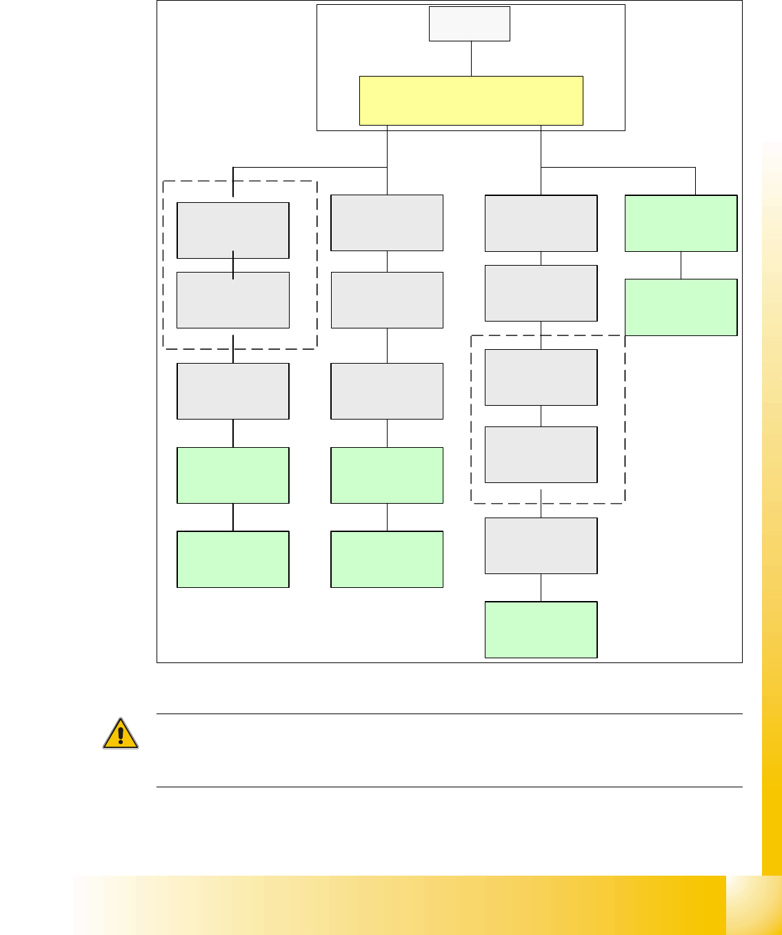
1.10.9.5 CAN Bus Siplace X3 (D3) (Variant 2)
Fig. 1.10 - 39 CAN bus structure X3 in line with operation diagram 00194418-02
Attention:
For the D3 machine you have this CAN Bus structure like the X3 machine, because D3 is a X3
machine with restrictions.
SMP BUS
Computer Unit
C
O
M
U
n
i
t
1
6
8
CAN Bus cable
PA1
X6pn
Trailing Interface
Gantry 1
Transport
Control unit
Axis unit
PA 1
CAN I/O
Sub Module
Sector 4
SUB Distributor Sector 4
Trailing Interface
Gantry 4
Head board(C500)
Gantry 4
Terminator
(120 OHM)
Head board(C500)
Gantry 1
Terminator
(120 OHM)
CAN Bus cable
PA 2
X7pn
Main Distributor Sector 2
Axis unit
PA 2
CAN I/O
Main Module
Sector 2
COT 2 / MTC 2
Tape cutter
Terminator
120 Ohm
Trailing Interface
Gantry 3
Head board(C500)
Gantry 3
Terminator
(120 OHM)
MC
Vision Control unit
only for stat.
Cameras up to
vers. 03)
Vision Control unit
(only for stat.
Cameras up to
vers. 03)
COT 1 Tape cutter
(optional stat.
Camera vers.04)
COT 4 Tape cutter
(optional stat.
Camera vers.04)
COT 3 Tape cutter
(optional stat.
Camera vers.04)
1 - 64
Siplace CAN Test Box
1 CAN Test Box Edition 04/2008
64
Fig. 1.10 - 40 CAN bus structure X3 operation diagram 00194418-02
X30_2tq X30_1tq
CAN
0301 0052
0301 0059
X6qf
X6qf
0304 1626
Patchkabel 3m
X5rk
X5rk
X3rk
X3rk
Verteiler
0304 0219
X2rk
X4rk
X1fq
X4rk
X1kq
X2rk
zum 1-Wire-Hub CAT5
zum 1-Wire-Hub CAT5
0304 1626
Patchkabel 3m
0304 1627
Patchkabel 3m
0304 1628
Patchkabel 3m
X6rf
X6rf
0301 0053
X15qa
X15qa
X15ra
X15ra
X1rk
X1rk
0300 9839
Verteiler
0304 0219 (qk)
X5qk
X5qk
X3qk
X3qk
X1hq
X4qk
X2qk
X2qk
zum 1-Wire-Hub CAT5
X1gq
X4qk
zum 1-Wire-Hub CAT5
0304 1627
Patchkabel 3m
0304 1628
Patchkabel 3m
X1qk
X1qk
0300 9826
Vision-Steuerung
00363 961 (qd)
CAN
Hauptverteiler 0301 0004 (qa)
X2qd
X2qd
CAN
X2qf
Einzug 2 Einzug 1
X125X126
CAN-InCAN-Out
X115X116
CAN-InCAN-Out
CAN
LP-Steuerung
X22ao
X22ao
CAN I/O-Modul 00355 051 (qb)
Bu
StBuSt
Bu
Bu
0301 0050
0301 0051
X2rd
X145
CAN-In
Bu
Bu
Achseinschub 2/3
0301 6110
X30_2sq
CAN
Einzug 3
X136
CAN-Out
St
X2rd
CAN
CAN
Unterverteiler 0301 0005 (ra)
Vision-Steuerung
00363 961 (rd)
Einzug 4
0301 0054
Computereinschub
X135
CAN-In
Bu
Bu
X68
Umgebungsdrucksensor
Pneumatikeinheit
Bestückbereich 2
Bestückbereich 1
CAN-Bus Aderbelegung
AderNr. Belegung Sub-D- PIN
1
2
3
4
5
6
7
8
9
CAN
X30_2sq
X30_1sq
Bu
X30_1sq
Bu
X30_2tq
Bu
X30_1tq
X146
CAN-Out
St
Interface 1-Wire CAT5
0304 1578 (qf)
X2qf
X2rf
CAN I/O-Modul 00355 051 (rb)
Bu
0304 1578
Interface 1-Wire CAT5 (rf)
X2rf
Achseinschub 1/4
0301 6110
CAN
0301 6643
X7pn X6pn
X7pn
Bu
CAN-Karte
X6pn
CAN-BUS 1CAN-BUS 2
Bu
GND
CAN_INT
PowerFail
frei
RESET
"1-Wire"
CAN_H
CAN_L
GND
3
9
5
8
4
2
7
6
1
1-Wire CAT5
1-Wire CAT5
(rk)
1-Wire CAT5 Portal
0304 2214 (he)
Schalterpos.: oben
CAN In
Bu
0302 7646
Abschlusswiderstand
120 Ohm
Bu
Schlepp Interface
Patchkabel 3m
0304 1629
P3
X1he
X1he
X40ca
X5he
X2he
X40ca
X4he
CAN
0301 0612
X40ba
St
X1
P4
1-Wire CAT5 Portal
X5ke
Schalterpos.: oben
0304 2214 (ke)
X40da
X4ke
CAN
X40da
Bu
CAN In
frei
X30_1sq
X1ke
X2ke
X2ke
0304 2214 (fe)
Schalterpos.: unten
X4fe
Schlepp Interface
Schlepp Interface
X40aa
CAN
(ca)
0301 0622
0301 0612
P1
(da)
(aa)
1-Wire Brücke
0304 2347
X2fe
X2fe
X5fe
1-Wire CAT5 Portal
X40aa
CAN In
Bu
X1fe
X1fe
Patchkabel 3m
0304 1629
Siehe Seite 3-20
Siehe Seite 5-35
Siehe Seite 5-28
Siehe Seite 3-13
e
Seite 5-72
Siehe Seite 5-35
Si
e
h
e
S
e
it
e
3
-
9
Siehe Seite 4-16
Siehe Seite 5-70
Siehe Seite 5-55
Siehe Seite 5-56
Siehe Seite 4-16
S
eite 5-27
Siehe Seite 5-55
Siehe Seite 5-73 Siehe Seite 5-73
Siehe Seite 5-72
Siehe Seite 5-73
Siehe Seite 5-70
1 - 65
Siplace CAN Test Box
Edition 04/2008 1 CAN Test Box
65
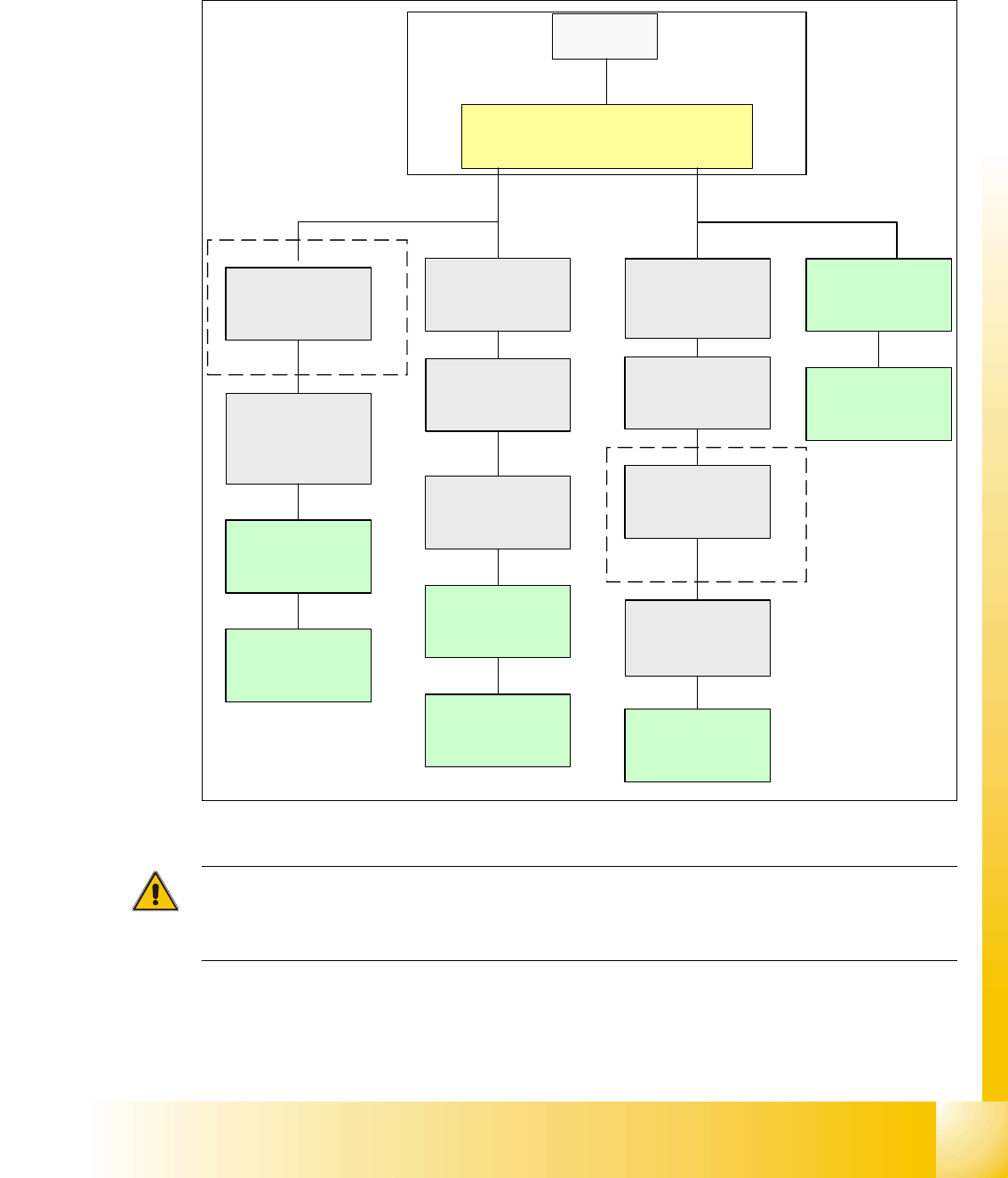
1.10.9.6 CAN Bus Siplace X3 (D3) (Variant 3)
All X-series machines from 2008 are delivered with CAN node to control the nozzlechanger and
their sensor with the CAN Bus again.
Fig. 1.10 - 41 CAN bus structure X3 variant 03
Attention:
For the D3 machine you have this CAN Bus structure like the X3 machine, because D3 is a X3
machine with restrictions.
SMP BUS
Computer Unit
C
O
M
U
n
i
t
1
6
8
CAN Bus cable
PA1
X6pn
Trailing Interface
Gantry 1
Transport
Control unit
Axis unit
PA 1
CAN I/O
Sub Module
SUB Distributor Sector 4
Trailing Interface
Gantry 4
Head board(C500)
Gantry 4
Terminator
(120 OHM)
Head board(C500)
Gantry 1
Terminator
(120 OHM)
CAN Bus cable
PA 2
X7pn
Main Distributor Sector 2
Axis unit
PA 2
CAN I/O
Main Module
Sector 2
COT 2 / MTC 2
CAN node
(Tape cutter, NC)
Terminator
120 Ohm
Trailing Interface
Gantry 3
Head board(C500)
Gantry 3
Terminator
(120 OHM)
MC
COT 4 / MTC2
CAN node
(Tape cutter, NC)
(optional stat.
Camera vers.04)
COT 3 / CAN node
(Tape cutter, NC)
(optional stat.
Camera vers.04)
COT 1 / CAN Node
(Tape cutter, NC
(optional stat.
Camera vers.04))