CAN Bus Workshop_Version 03__06-2008_EN.pdf - 第296页
1 - 88 Siplace C AN T est Box 1 CAN T est Box Edition 04/200 8 88 Comments :
1 - 87
Siplace CAN Test Box
Edition 04/2008 1 CAN Test Box
87
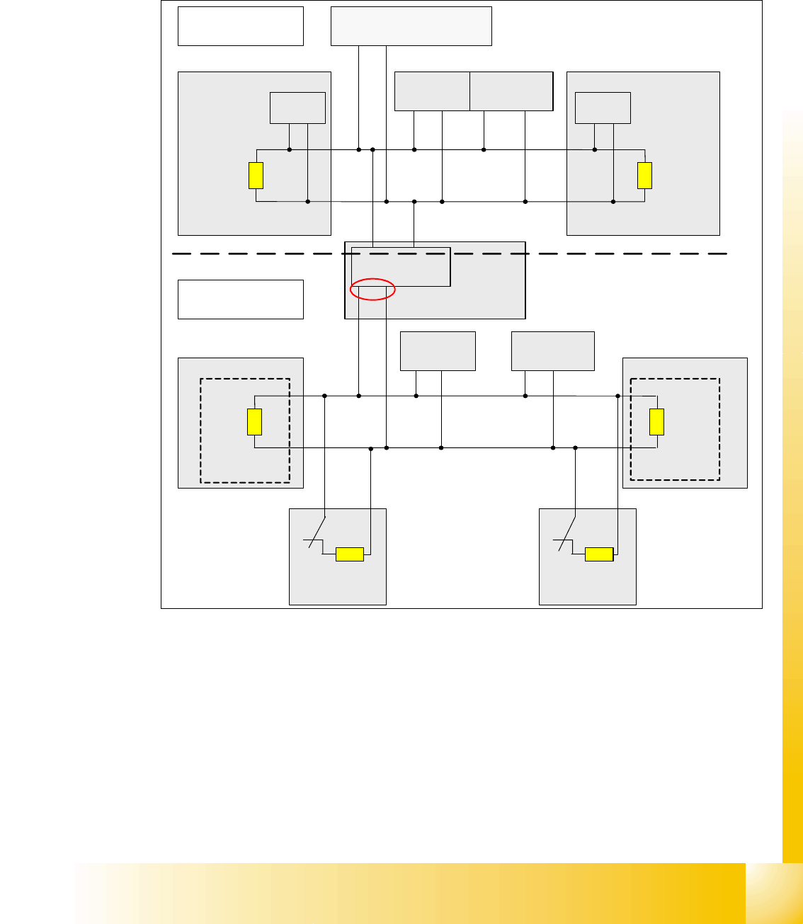
CAN Bus with CAN Terminator on the D4 in detail 1
For the D-Series machine we use two different CAN BUS circuits with a different speed. The ma-
chine CAN BUS with 1Mbit/s and the CAN BUS for the component table and tape cutter with 500
kbit/s. The speed of the CAN BUS will be reduce on the CAN Interface board which is located on
the CAN I/O module.
Fig. 1.10 - 63 CAN Bus in detail for example PA1 D4 machine
Note to measure the CAN terminator:
In General, the terminator has to measure if the machine switch off!
In the Fig. 1.10 - 63 for the component and tape cutter CAN BUS (500kBit/s), there are four ter-
minators in the circuit, if the machine switch off and the component table connected. So you mea-
sure on position (1) 30 ohm.For the machine CAN Bus (1MBit/s) you measure 60 ohm
When the machine is switch on, the Relays contacts K1 will be open and the normal termination
of 60 Ohm is available. Now, If you change or disconnect a component table, the CAN BUS is
working normal, because the relay contact K1 will be closed and the other terminator is available .
Component Table 1Component Table 4
Gantry head distributer
Gantry 4
TQ M
CAN_H igh
CAN_Low
Machine CAN Bus
1 Mbit/s
CAN Bus for
Component table and
tape cutter 500 kbit/s
Axis unit 1/4
PA 1
Transport
control unit
Micro BOX PC
(Machine controller)
Gantry head distributer
Gantry 1
TQ M
CAN_H igh
CAN_Low
CAN
I/O module
sector 4
CAN Interface
500 KBit/s
CAN_High
CAN_Low
CAN_High
CA N_ Lo w
Com. unit
Tape cutter
Location 1
Tape cutter
Location 4
Com. unit
CAN Bus
Terminator
Comp.table 1
CAN Bus
Terminator
Comp.table 4
120 Ohm120 Ohm
120 Ohm
120 Ohm
Relays
contact K1
Relays
contact K1
1

1 - 88
Siplace CAN Test Box
1 CAN Test Box Edition 04/2008
88
Comments: