CAN Bus Workshop_Version 03__06-2008_EN.pdf - 第54页
1 - 28 S tudent Gu ide CAN BUS Wor kshop 2 Commun icatio n and C ontrol Editio n 06/200 8 28 2.2.9 CAN: Bus Communication with Axis Controller In prev ious Si place p lacem ent ma chin es, th e com munic ation an d data …

1 - 28
Student Guide CAN BUS Workshop
2 Communication and Control Edition 06/2008
28
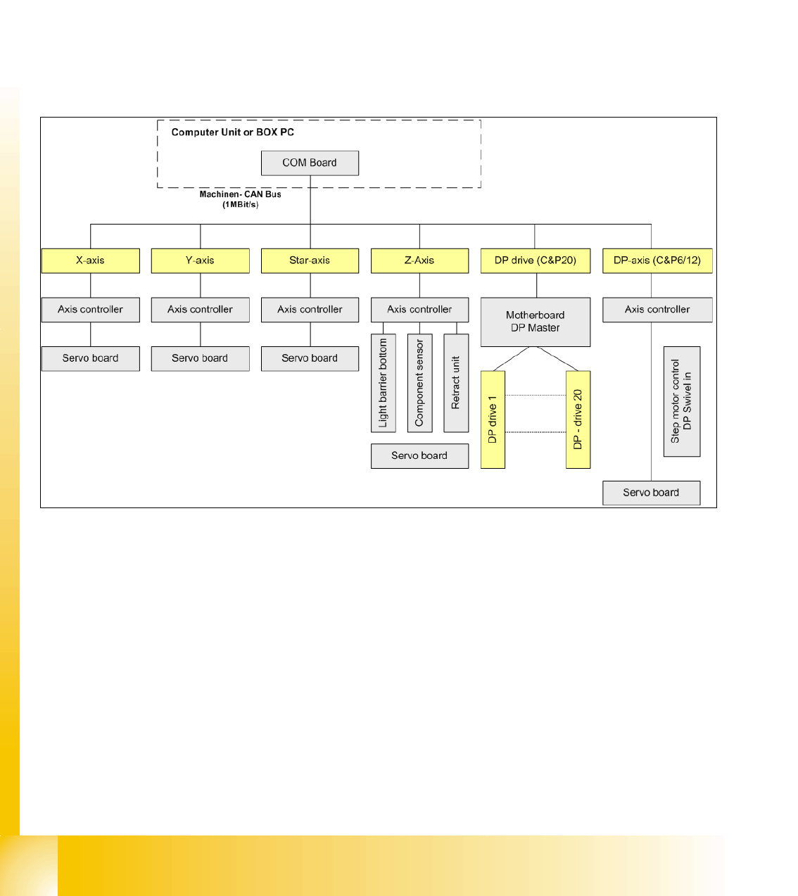
2.2.9 CAN: Bus Communication with Axis Controller
In previous Siplace placement machines, the communication and data flow between axis control-
ler and machine controller was achieved using the SMP bus. From the HF machine generation
on, the SMP bus is no longer used with the axis system.
The communication between the axis controller modules is now achieved using the CAN Bus. All
information, which has to be transfered between these modules, is now on the CAN bus (e.g axis
parameter, target position, end signal, ...) This of course means that the number of single tele-
grams increases significantly compared with the amount of data exchange which has occurred
previously.
Fig. 2.2 - 20 Overview axis controller
1 - 29
Student Guide CAN BUS Workshop
Edition 06/2008 2 Communication and Control
29
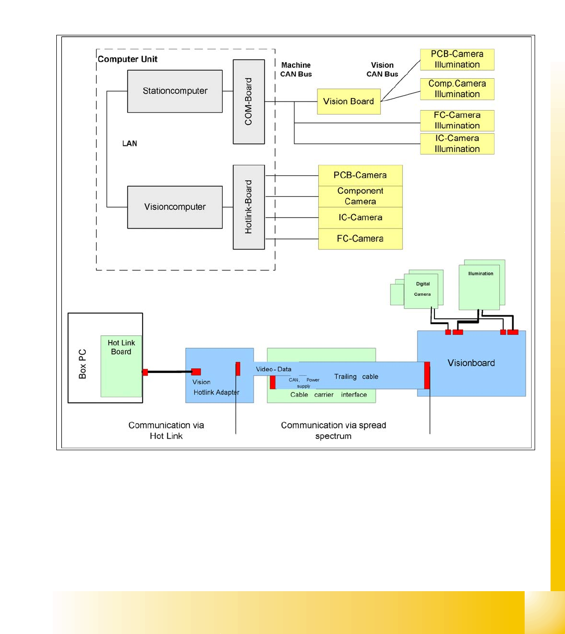
2.2.10 Communication Siplace Vision
The communication between the computers is via LAN cables. The station computer sends the
commands for image acquisition to the Vision computer and receives the measurement result.
The station computer also sends the illumination values for the respective component shapes.
The images recorded are transferred digitally via the Vision board to the hotlink adapter, using the
spread spectrum and are then sent via the hotlink connection to the Vision computer, for
evaluation. The result is sent to the station computer.
Fig. 2.2 - 21 Overview Siplace Vision