CAN Bus Workshop_Version 03__06-2008_EN.pdf - 第43页
1 - 17 S tudent Guide CAN BUS W orkshop Edition 0 6 /2008 2 Comm unication and Control 17 2.2.6.3 Siplace X3 with CA T 5 and CAN node (e.g. P A 1) The new Sipla ce X-m achin e togeth er with t he X4I machine the O ne Wi …
1 - 16
Student Guide CAN BUS Workshop
2 Communication and Control Edition 06/2008
16
2.2.6.2 Siplace X3 with CAT 5 (e.g. PA 1)
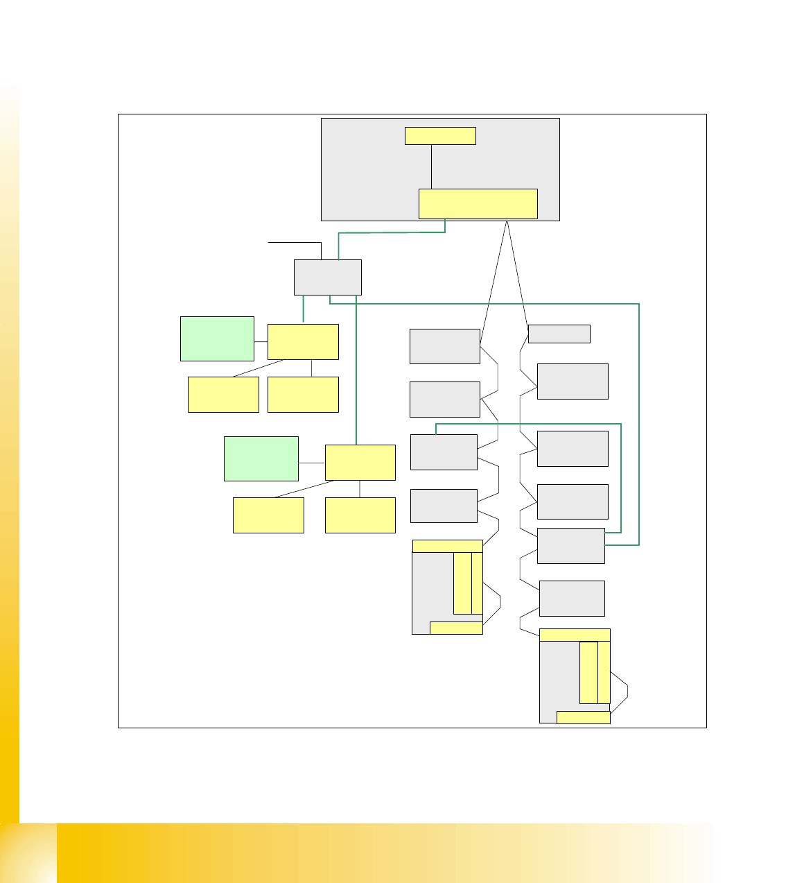
With the Siplace X-machine the One Wire Bus is integreted in a separate CAT5 cabel, which start
from the Main- and Subdistributor up to the trailling interface. On the Main- and Subdistributor are
installed the control unit of the one wire system. A kind of switch are located on the other units
which required the one wire system (see figure below). This switch open and close the communi-
cation path. Controlled components with the ONE Wire Bus:
– Nozzle changer of the C&P heads
– Temperature sensors
– Gantry recognition (CFK02, CFK04, CFK06)
– Option Reject Box
Fig. 2.2 - 14 General overview One Wire Bus with CAT 5 cable in a Siplace X3
Cat 5 (english category), is a Twisted-Pair-cabel, for data transfer.
Vision control
unit
Sector 4
Transport
Control unit
Axis unit
PA 1
COM Board
I/O SUB Module
Sector 4
One Wire Bridge
(driver)
Nozzle changer
Hub (Coupler)
Gantry 4
CO-Table 4
Tape cutter
Conrol board
NC (C&P20)
row 1
Control board
NC (C&P20)
row 2
Trailing -Interface
Gantry 4
CO-Table 1
Tape cutter
Trailing-Interface
Gantry 1
Temp.sensor
Head
plate
Temp.sensor
Option: Check reject bin
or terminating plug
Attention: no CAN-
termination resistor
TQM Module
(Master)
RS232
Machine CAN Bus
1 Wire CAT5
Gantry 4
Headinterface
1 Wire CAT5
Gantry 4
Temp.sensor
Head
plate
Temp.sensor
Gantry
recognition
Headinterface
1 Wire CAT5
Distributor
24V for the nozzle changer
1 Wire CAT5 cable
1 Wire CAT5 cable
1 Wire CAT5 cable
1 Wire CAT5 cable
1 Wire CAT5 cable
Nozzle changer
Hub (Coupler)
Gantry 1
Control board
NC (C&P20)
row 2
Conrol board
NC (C&P20)
row 1
Option: Check reject bin
or terminating plug
Attention: no CAN-
termination resistor
Gantry
recognition
1 - 17
Student Guide CAN BUS Workshop
Edition 06/2008 2 Communication and Control
17
2.2.6.3 Siplace X3 with CAT 5 and CAN node (e.g. PA 1)
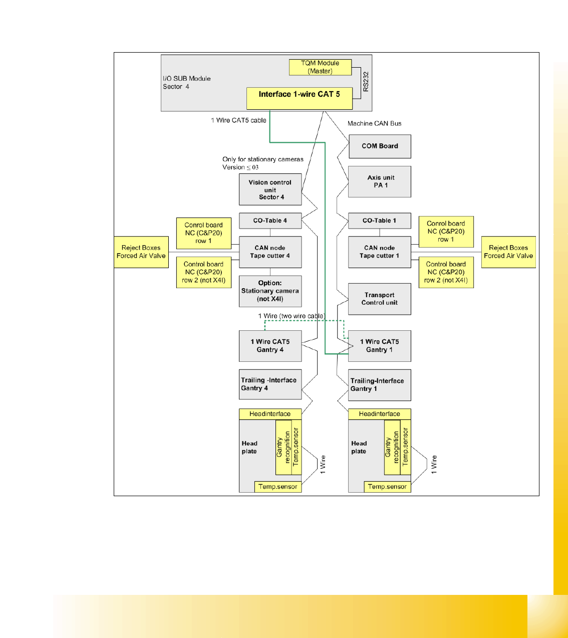
The new Siplace X-machine together with the X4I machine the One Wire Bus is now responsible
to control the temperature sensors on the head plates only (see figure below).
The introduction of the SIPLACE X4I and the further development of the SIPLACE X series also
brings with it the integration of the nozzle changer control and the monitoring sensors into the
machine CAN bus.
This new board is named "CAN node NC tape cutter module" [03052927-xx] and is used in place
of the former tape cutter board.
Fig. 2.2 - 15 General overview CAN-Bus with One Wire and CAN node e.g.Siplace X3 PA1
1 - 18
Student Guide CAN BUS Workshop
2 Communication and Control Edition 06/2008
18
2.2.7 CAN Bus Processor Board C&P Head
Can bus processor board TQM 167 LC is mounted on the head board C500. The processor board
is used at different places in the machine.
If the processor board on the head board, the firmware provides at the processor board the control
of the head specific actors and sensors no matter which head type is installed.
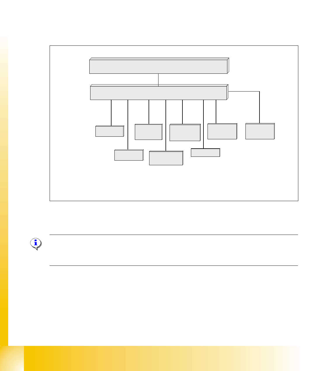
2.2.7.1 CAN Bus controlled function on 6/12C&P Head
The following overview shows various head functions, controlled by the CAN system. Thus, the
CAN bus controls the actuators and sensors of the C&P Head.
Fig. 2.2 - 16 CAN function on C&P Head
NOTE:
The status of the 16 Bit PROCESSOR BOARD is indicated on the 7-segment display.
Normal status on the diplay is: Display shows slowly flashed " . "
Comp.-sensor
CAN Bus 16 bit Processor Board
stepper motor
reject
:
LS top
LS bottom solenoid valve
air kiss
:
CAN bus
stepper motor
swivel in Dp
stepper motor
pick up / place
Vacuum values
Communication Board
LS = Light barrier