CAN Bus Workshop_Version 03__06-2008_EN.pdf - 第287页
1 - 79 Siplace C AN T est B ox Edition 04 /2008 1 CAN T est Box 79 CAN Bus with CAN T erminator on the D1 in det ail 1 For the D 1 machine we use tw o different CAN BU S circui ts. CAN BUS 1 is wor king with 1 MBit/ s an…
1 - 78
Siplace CAN Test Box
1 CAN Test Box Edition 04/2008
78
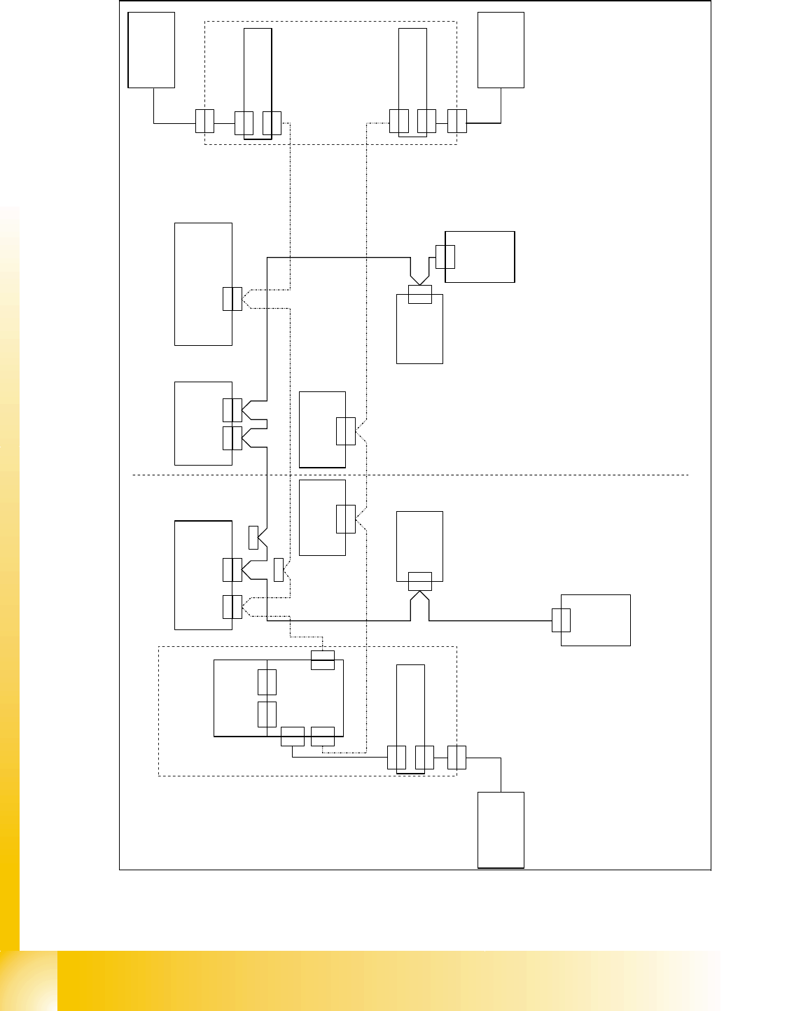
Fig. 1.10 - 54 CAN bus structure D1 operation diagram 03043799-010302LD3
C A N T e r m i n a t i o n o n :
S 1 . 8 = O N
C A N T e r m i n a t i o n o f f :
S 1 . 5 = O F F
f i x e d C A N T e r m i n a t i o n o n
G a n t r y H e a d B o a r d
0 3
0 3 8 0 0 2
C A N I / O m o d u l e
0 0 3 5 5 0 5 1 ( q b )
B E - T i s c h 2
C o m p o n e n t s t a b l e 2
0 3 0 4 1 3 1 5 )
M a s c h i n e n C o n t r o l l e r
M a c h i n e c o n t r o l l e r
0 3 0 3 2 3 4 2 ( p a )
C A N - B u s 1 D 1
C A N - B u s 2 D 1
A x i s U n i t A 3 6 4
0 3 0 4 2 0 4 7
T r a n s p o r t s t e u e r u n g T S P 2 0 1
C o n v e y o r c o n t r o l l e r T S P 2 0 1
0 3 0 4 3 8 3 2
C A N 2 C A N 1
X 2 2 a o
X 2 2 a o
X 3 0 _ 1 s q
X 3 0 _ 1 s q
X 1 1 p aX 1 2 p a
X 1 1 p aX 1 2 p a
X 1 b f
H a u p t v e r t e i l e r
M a i n D i s t r i b u t o r
0 3 0 5 0 1 7 8 ( b f )
U n t e r v e r t e i l e r
S u b D i s t r i b u t o r
0 3 0 4 8 9 6 6 ( a f )
B E - K a m e r a S t a t .
P + P ( T Y P 3 6 )
5 5 x 4 5 d i g i t .
0 3 0 4 2 4 9 1
B E - K a m e r a S t a t .
P + P ( T y p 2 5 )
1 6 x 1 6 d i g i t .
0 3 0 2 0 5 7 8
S c h l e p p -
V e r t e i l e r
T r a i l i n g
d i s t r i b u t o r
0 3 0 3 8 6 9 0
X 4 0 a a
X 4 0 a a
X 1 b f X 1 a f
X 1 a f
X 1 0 b u
X 3 0 _ 2 s q
X 3 0 _ 2 s q
A b s c h l u s s -
w i d e r s t a n d
T e r m i n a t i n g
r e s i s t o r
0 3 0 2 7 6 4 6
0 3 0 5 0 1 6 2
0 3 0 5 0 1 6 4
X 1 q f
X 1 0 3
X 1 1 p a 2
X 1 2 p a 2 S e r v i c e
S e r v i c e
X 1 0 b u
X 1 0 a u
X 1 0 a u
P o r t a l 1 / G a n t r y 1
S e k t o r 2
S e c t o r 2
S e k t o r 1
S e c t o r 1
C A N - B u s 2 S u b
0 3 0 5 0 1 6 5
X 1 q b
X 1 q e
C A N - I n t e r f a c e
0 3 0 3 2 3 4 6 ( q e )
X 4 b h
X 4 b h
X 3 q e
X 3 q e
X 5 q e
X 5 q e
X 4 q e
X 4 q e
G u r t s c h n e i d e r 2
T a p e c u t t e r 2
0 3 0 0 6 4 1 1 ( b h )
G u r t s c h n e i d e r 1
T a p e c u t t e r 1
0 3 0 0 6 4 1 1 ( a h )
X 1 r b
X 1 r b
X 2 r b
X 2 r b
B E - T i s c h 1
C o m p o n e n t s t a b l e 1
0 3 0 4 1 3 1 5
X 3 0 a f
X 3 0 a f
W a f f l e P a c k
C h a n g e r
0 3 0 4 6 8 1 6
X 2 r d
X 2 r d
X 1 r d
X 1 r d
C A N - B U S t e r m i n a t o r
c o m p o n e n t t a b l e
0 3 0 4 6 8 6 3
C A N - B U S t e r m i n a t o r
c o m p o n e n t t a b l e
0 3 0 4 6 8 6 3
X 4 a h
X 4 a h
X 1 q a
X 1 q a
X 2 q a
X 2 q a
C A N - B U S t e r m i n a t o r
c o m p o n e n t t a b l e
0 3 0 4 6 8 6 3
X 2 q b
X 2 q e
1 - 79
Siplace CAN Test Box
Edition 04/2008 1 CAN Test Box
79
CAN Bus with CAN Terminator on the D1 in detail 1
For the D1 machine we use two different CAN BUS circuits. CAN BUS 1 is working with 1 MBit/s
and CAN BUS 2 is cut in to areas with a different speed. One part of the CAN BUS 2 works with
1Mbit/s and the CAN BUS for the component table and tape cutter with 500 kbit/s. The speed of
the CAN BUS 2 will be reduce on the CAN Interface board which is located on the CAN I/O module
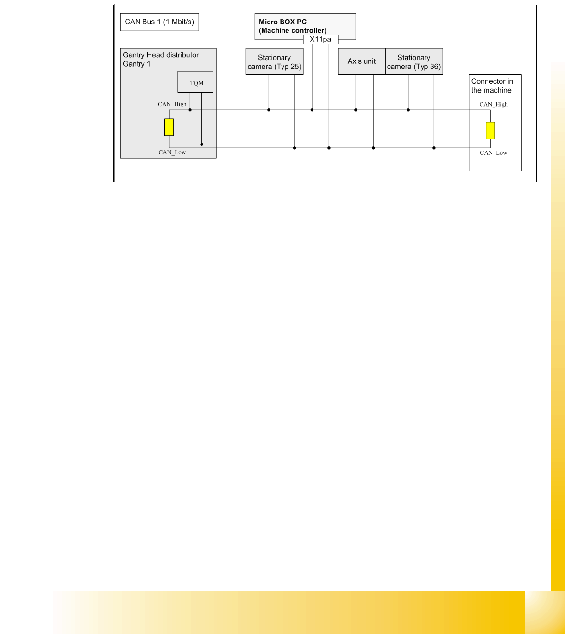
Fig. 1.10 - 55 CAN Bus 1 in detail D1 machine
Note to measure the CAN terminator:
In General, the terminator has to measure if the machine is switch off!
In the Fig. 1.10 - 55 for the CAN BUS 1, there are two terminators in the circuit, When the machine
is switch off you have to measure on the serviceconnector X11pa2 a value of 60 Ohm.
1 - 80
Siplace CAN Test Box
1 CAN Test Box Edition 04/2008
80
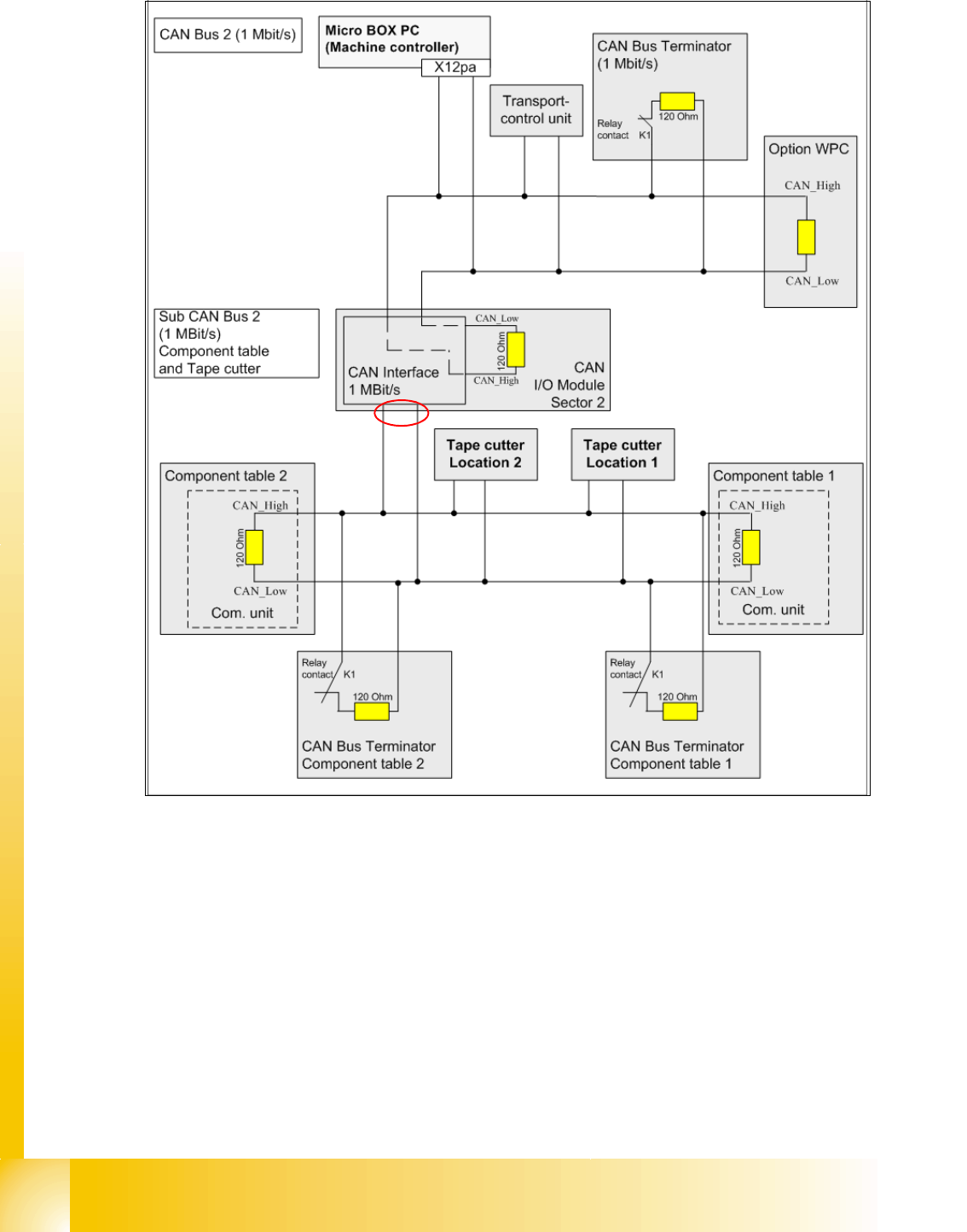
Fig. 1.10 - 56 CAN Bus 1 in detail D1 machine
For the CAN BUS 2 (1MBit/s) you have to measure the terminator on the serviceconnector
X12pa2. If the option WPC connected you should measure 40 ohm, if not the value is 60 ohm.
In the Fig. 1.10 - 56 for the component and tape cutter CAN BUS 2, there are four terminators in
the circuit, if the machine switch off and the component table connected. So you measure 30 ohm
on the connector (1).
When the machine is switch on, the Relays contacts K1 will be open and the normal termination
of 60 Ohm is available.
Now, If you change or disconnect a component table, the CAN BUS is working normal, because
the relay contact K1 will be closed and the other terminator is available.
1