CAN Bus Workshop_Version 03__06-2008_EN.pdf - 第213页
1 - 5 Siplace C AN T est B ox Edition 04 /2008 1 CAN T est Box 5 1.3 CAN Bus Signal Assignment Fig. 1.3 - 1 Signal assignment at the different connectors – C AN_INT – not in use ( +5V) – Power Fail – trigger s reco rdin …
1 - 4
Siplace CAN Test Box
1 CAN Test Box Edition 04/2008
4
1.2 General
The CAN Test Box is a tool for service technicians to test basic CAN bus functions at SIPLACE
machines. This CAN Test Box can be used on machines implementing a CAN bus with a baud
rate of 500 kBit or 1 MBit. Although the CAN Test Box can also be used for the slower CAN bus
(125kBit) on HS50/60 machines, the Error Frame Counter will not function in this case.
The following functions can be checked:
– Terminating resistors
– Recessive voltage levels
– Dominant voltage levels
– Power fail voltage level, CAN reset
– Error frames
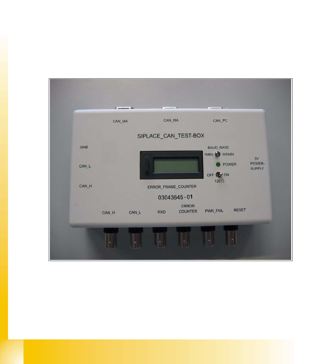
Fig. 1.2 - 1 CAN Test Box
Ordernumber Siplace CAN Test Box: 03043645-01
Content: CAN Test Box, cable Power supply 5 V, CAN Bus Test cable 1,5m,
CAN Bus Test cable 0,75m, CAN Bus Test cable with 10 pins e.g. Tyco connector 0,5m.
CAN Test cable with the Ordernumber 00349679-03 could order additionally!
1 - 5
Siplace CAN Test Box
Edition 04/2008 1 CAN Test Box
5
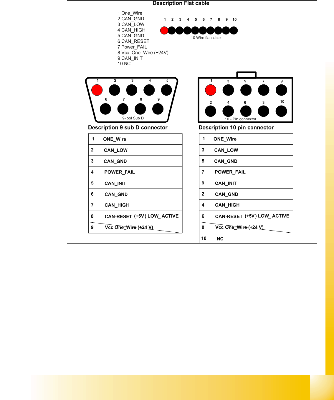
1.3 CAN Bus Signal Assignment
Fig. 1.3 - 1 Signal assignment at the different connectors
– CAN_INT – not in use (+5V)
– Power Fail – triggers recording of operating data at the placement head (+5V)
– CAN RESET – not in use (+5V) (HS50/60 use the signal for the Tape cutter and component
table)
– CAN HIGH - 2,5 +/– 0,3 V recessive level (machine in idle mode)
– CAN LOW - 2,5 +/– 0,3 V recessive level (machine in idle mode)
– CAN GND - Can bus ground
– Vcc 24V - for nozzle changers - no longer available after the above mentioned conversions
– One wire - only applies to HF series, in the machine CAN bus cable
1 - 6
Siplace CAN Test Box
1 CAN Test Box Edition 04/2008
6
1.4 CAN Test Box Connections
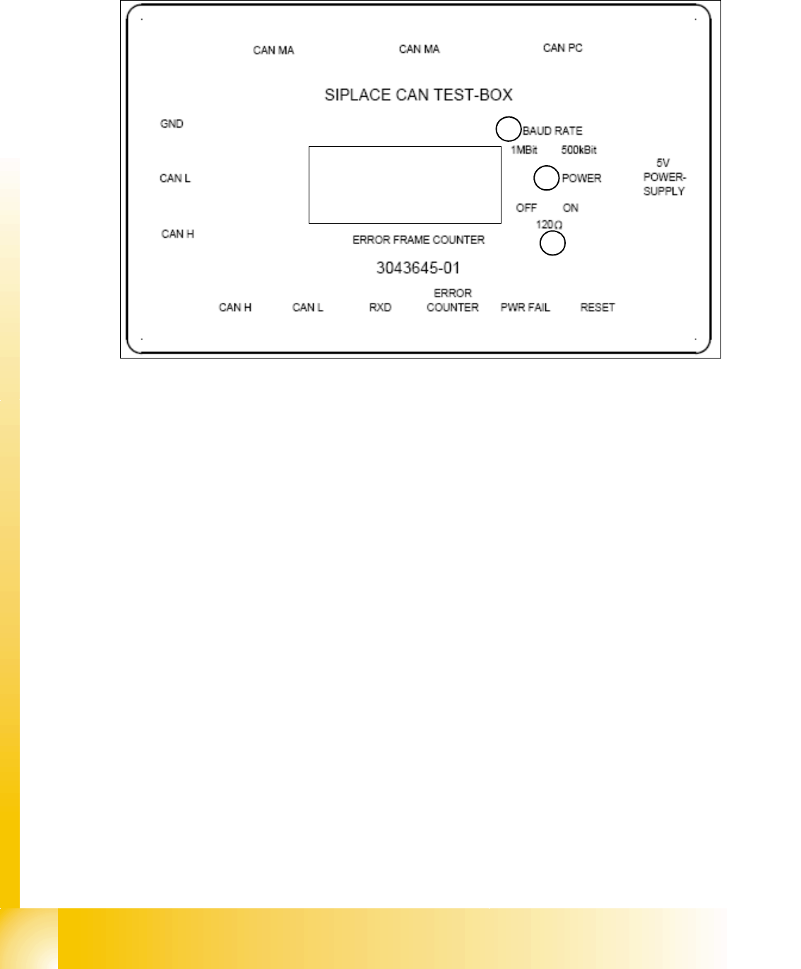
Fig. 1.4 - 1 CAN Test Box connections
(1) Switch for setting the baud rate to 1 MBit or 500 kBit
(2) Switch for enabling an additional 120 Ohm resistance.
(3) Power LED to show the power supply state (green = power on)
– 5V voltage supply from the axis card or external power pack
– CAN BUS PC connection PC (Sub D female connector). Only the CAN High, CAN Low and
GND signals are run to the PC (Kvaser card), preventing PC-card corruption.
– CAN BUS_MA connection to the machine, COM assembly (Sub D female connector)
– CAN BUS_MA connection to the machine, COM assembly (Sub D male connector)
– Banana jack for CAN High measurement of recessive CAN bus level against CAN GND
– Banana jack for CAN Low measurement of recessive CAN bus level against CAN GND
– Banana jack for CAN GND ground CAN bus
– BNC socket for CAN High
– BNC socket for CAN Low
– BNC socket RxD shows the combination of CAN High and CAN Low signals to a TTL level, as
read by the CAN telegram processor.
– BNC socket for Error Counter from display
– BNC socket for power fail to check of the level in the line (4,0 - 5,0 V).
– BNC socket for CAN reset to check of the level in the line (4,0 - 5,0 V).
Error Frame Counter
Display
1
3
2