CAN Bus Workshop_Version 03__06-2008_EN.pdf - 第141页
CACCIA Manual 1 Caccia Student Guide Issue 04/2007 EN 49 T ab. 1 - 17 Name - subsystem 1 CO t ables and t ape cutter 1 K Processor for he ad board (8 or 16 Bi t), Head processor (TQM module) DLM heads 1 K02 for st and. h…
1 Caccia Student Guide CACCIA Manual
Issue 04/2007 EN
48
1.6.4 Download - File Code
The download files have a fixed structure. 1
The following example illustrates the file naming convention: 1
B011031B.hex 1
1
Tab. 1 - 16 File name structure
1
The Name indicates the subsystem type: 1
1
File name Category Meaning
BName CO table file
0 Variant ID No variant (0)
1 Hardware ID 1 Hardware state 1 1
1Target
0 would mean BIOS
1 mean Application 1
2 would mean Application 2
03 Version Version 003
1B Release
Release 27 (1B
H
→ 27
D
)
.
Separator 1 Separator between file name
and file extension 1
HEX
File type 1 File extension, file format
HEX file 1
Name Meaning Comments
A
Axis controller in General
The description is valid for sepatrated axis
types too)
01 for Axis controller A362
03 for Axis controller 363
04 for Axis controller 364
B Controller on CO table
01 for HM/HS machines
02 for HF machines
04 for X machines
C Star axes, C&P20
D D axes, DLM2 heads 11
E I/O module controller
F Axis controller, free axis
G Tape cutter
01 for HS machines
02 for HF machines
H
Head functions, C&P20 1 Head processor
(TQM module) 1
I Twin head (segment 1 or 2) 11
J DP axes (master), C&P20 11

CACCIA Manual 1 Caccia Student Guide
Issue 04/2007 EN
49
Tab. 1 - 17 Name - subsystem
1
CO tables and tape cutter
1
K
Processor for head board (8 or 16 Bit),
Head processor (TQM module) DLM
heads 1
K02 for stand. h.board S/F
K03 for stand. h.board HS50
K04 for modulare Kopfplatine
HS/S/F
K05 8Bit proc. HF-head adap.
K06 16Bit-processor HF/X/..
K07 heads on D4/D2/D1 1
L
Digital pressure control valve, C&P20 and
Twin head 1
Vacuum generator 1
M MTC 11
P Twin Z-axis controller 11
R Twin D axis controller 11
S Star axes, DLM heads 11
T
Conveyor control (ger. TSP) 1 T01 for HS50 with TSP100
T02 for HS50 with TSP200
T03 for S25/F5HM
T04 for S27HM/D2/1 TSP201
T05 for HSxx/D4 mitTSP301
T06 for X / D3 with TSP3011
UA X-feeder which has been set up 11
UB
Special feeder using a X-Adapter to
COT-table 1
1
V
Vision controller, subboards for head inter-
face 1
start with version 05 1
W Z-axes, C&P20 11
X X-axes 11
Y Y-axes 11
Z Z-axes, DLM heads 11
System name
BIOS version
system boot data
Application 1
system firmware
Comments/ news
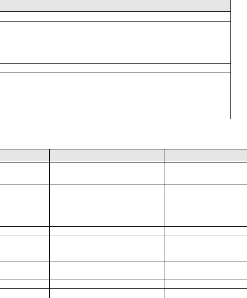
Conveyor 1/2 0.6.03.03 0.6.05.21
Tape cutter 0.2.01.00 0.2.01.00
CO table, (S, X) 0.2.01.01 0.2.01.02 11
FCU HW 4 0.4.02.00 0.5.01.01
Different HW requires differ-
ent SW
Name Meaning Comments
1 Caccia Student Guide CACCIA Manual
Issue 04/2007 EN
50
Tab. 1 - 18 BIOS and Application Firmware versions as an example for several X-Ma. Components
1
Placement heads and Vision control
1
Tab. 1 - 19 BIOS and Application1 eSW on Placement heads and Vision control
Axis controller
1
X-feeder 0.1.00.04 0.1.00.15 Fast feeder for C&P20
I/O modules 0.1.02.10 0.1.02.12
MTC 2 0.2.02.00 0.2.02.01 11
System name
BIOS version
system boot data
Application 1
system firmware
Comments/ news
C&P 6/12 heads (16
Bit)
0.1.01.0C 0.6.01.09 16 Bit head processor
C&P20 heads 0.1.01.02 0.1.01.0E New placement head
Twin head, both
segments (16 bit)
0.1.03.25
0.1.02.02 1 Common head processor 1
Vision board for
PCB C&P CO cam-
era
0.5.03.04 0.5.02.06
Vision Board for IC
FC camera
0.5.03.04 0.5.02.06 Twin head illumination control
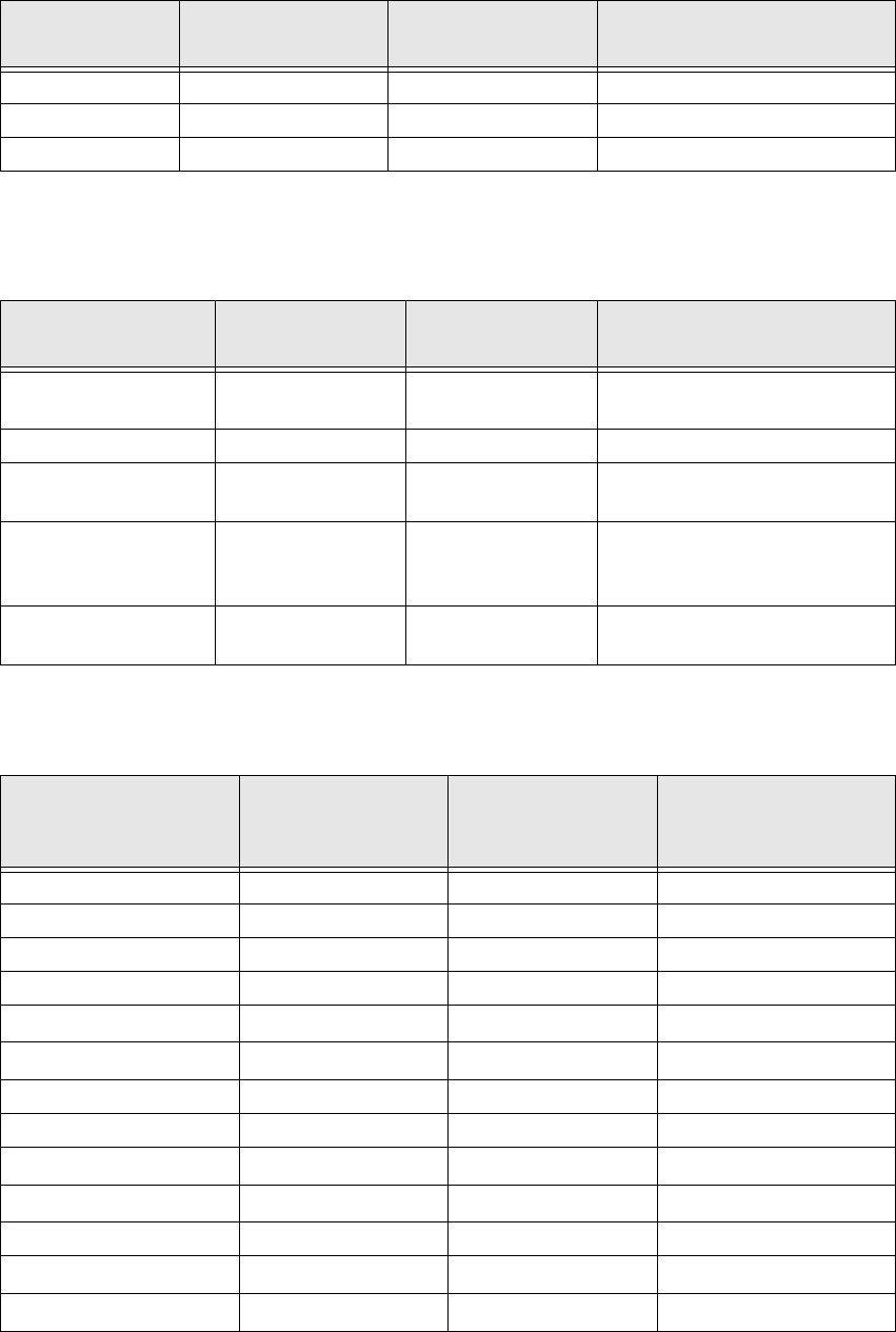
Axis type
BIOS version
system boot data
Application 1
firmware for axis
main board
Application 2
firmware for VC3
controller
X 03.02.00 03.FB.69 03.02.23
Y 03.02.00 03.FB.69 03.02.23
C&P20 1
Star 03.02.00 03.FB.69 03.02.23
Z
C&P
03.02.00 03.FB.69 03.02.23
DP
C&P
---
C&P &/12
Star 03.02.00 03.FB.69 03.02.23
Z
C&P
03.02.00 03.FB.69 03.02.23
DP
C&P
03.02.00 03.FB.69 03.02.23
Twin
Z
Twin
03.02.00 03.FB.69 03.02.23
DP
Twin
03.02.00 03.FB.69 03.02.23
System name
BIOS version
system boot data
Application 1
system firmware
Comments/ news