CAN Bus Workshop_Version 03__06-2008_EN.pdf - 第45页
1 - 19 S tudent Guide CAN BUS W orkshop Edition 0 6 /2008 2 Comm unication and Control 19 2.2.7.2 CAN-Bus control led functi on on C&P 20 Kop f The foll owing ov erview s hows various head functions , contro lled by …
1 - 18
Student Guide CAN BUS Workshop
2 Communication and Control Edition 06/2008
18
2.2.7 CAN Bus Processor Board C&P Head
Can bus processor board TQM 167 LC is mounted on the head board C500. The processor board
is used at different places in the machine.
If the processor board on the head board, the firmware provides at the processor board the control
of the head specific actors and sensors no matter which head type is installed.
2.2.7.1 CAN Bus controlled function on 6/12C&P Head
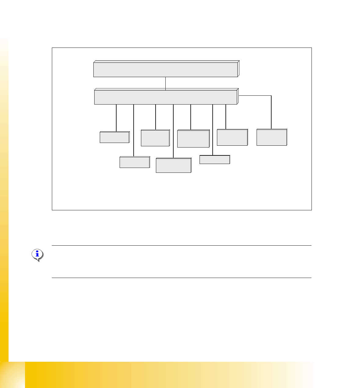
The following overview shows various head functions, controlled by the CAN system. Thus, the
CAN bus controls the actuators and sensors of the C&P Head.
Fig. 2.2 - 16 CAN function on C&P Head
NOTE:
The status of the 16 Bit PROCESSOR BOARD is indicated on the 7-segment display.
Normal status on the diplay is: Display shows slowly flashed " . "
Comp.-sensor
CAN Bus 16 bit Processor Board
stepper motor
reject
:
LS top
LS bottom solenoid valve
air kiss
:
CAN bus
stepper motor
swivel in Dp
stepper motor
pick up / place
Vacuum values
Communication Board
LS = Light barrier
1 - 19
Student Guide CAN BUS Workshop
Edition 06/2008 2 Communication and Control
19
2.2.7.2 CAN-Bus controlled function on C&P 20 Kopf
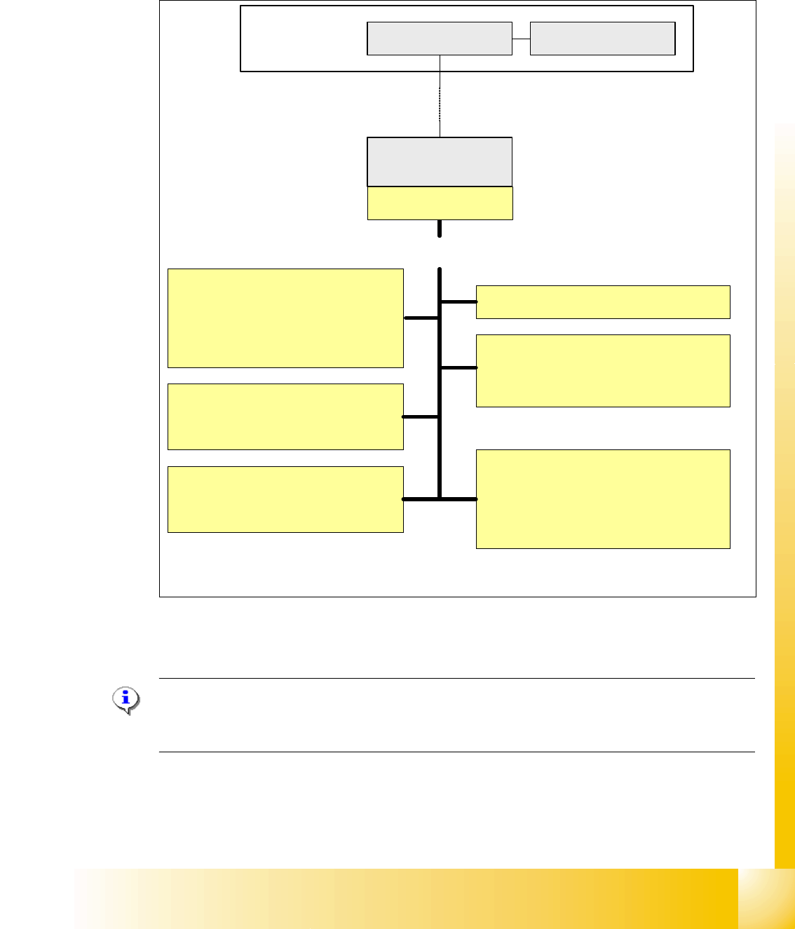
The following overview shows various head functions, controlled by the CAN system. Thus, the
CAN bus controls the actuators and sensors of the C&P Head.
Fig. 2.2 - 17 Communication TQM Modul on the C&P 20 head
NOTE:
The status of the 16 Bit PROCESSOR BOARD is indicated on the 7-segment display.
Normal status on the diplay is: Display shows slowly flashed " . "
Pick up/Placement position
1. Adjust vacuum/air kiss
2. Measurement vacuum/air kiss
3. Reject function
Holding circuit
1. Monitoring vacuum
2. Measurement vacuum
Component Sensors
1. Initialization
2. Calibration
EEPROM
1. Zero point correction Z-axis
2. Zero point correction Star-axis
3. other head specific data
Computer Unit
COM Board
Machine- CAN Bus
(1MBit/s)
MC
Head processor
C500
TQM-module
Light barrier bottom
1. Activate the light barrier
Function control light barrier bottom
directly on the axis controller A363
Control Head-Can Bus
Control of the following functions
Function control component
sensor directly on the axis
controller A363
TQM = TQ Company name
M = module
TQM = 16 bit processor
1 - 20
Student Guide CAN BUS Workshop
2 Communication and Control Edition 06/2008
20
2.2.7.3 CAN Bus controlled function on the Twin Head
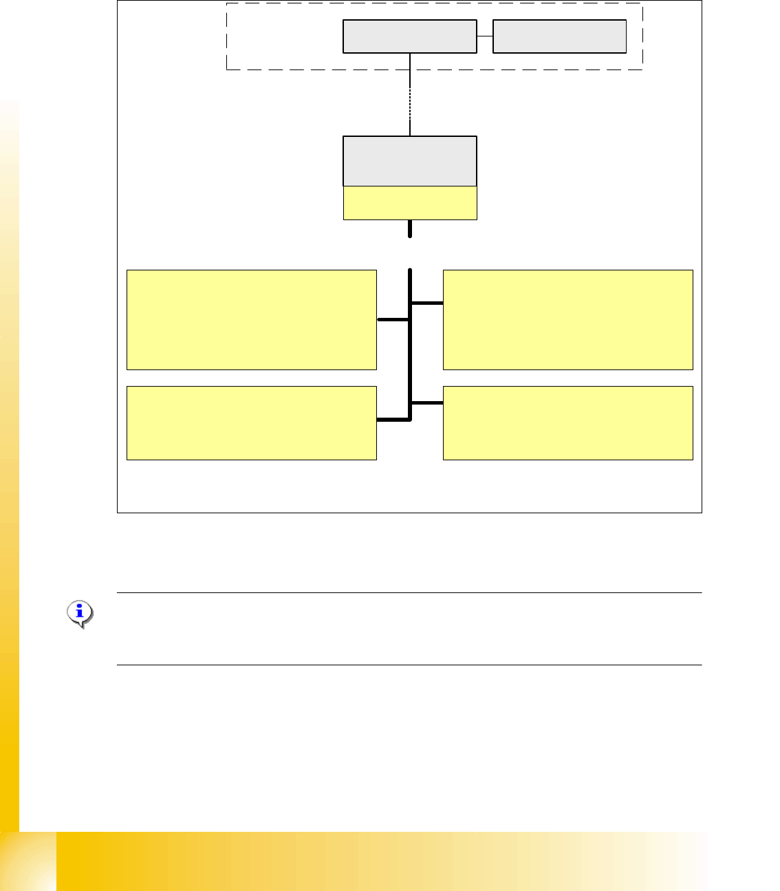
The CAN-Bus Processor-board is no longer on each Twin segment installed. Now, the Twin seg-
ment got a new board and the processor board (TQM) is installed on the head board C500. The
reason is, that we have a defined interface for head modularity.
Fig. 2.2 - 18 Function on the Can Bus Processor Twin Head
NOTE:
The status of the 16 bit PROCESSOR BOARD is indicated on the 7-segment display.
Normal status on the diplay is: " . " flashed
Vacuum/Air kiss generator Segment 1
1. Adjust vacuum/air kiss
2. Measurement vacuum/air kiss
3. Reject function
Computer Unit
COM Board
Machine- CAN Bus
(1MBit/s)
Control of the following functions
MC
Head processor
C500
TQM-module
Force measurement board Segment 1
1. Activation
Function control force measurement
directly on the axis controller A363
Vacuum/Air kiss generator Segment 2
1. Adjust vacuum/air kiss
2. Measurement vacuum/air kiss
3. Reject function
Force measurement board Segment 2
1. Activation
Function control force measurement
directly on the axis controller A363