CAN Bus Workshop_Version 03__06-2008_EN.pdf - 第75页
1 - 13 S tudent Guide CAN BUS W orkshop Edition 06/20 08 3 CAN B US 13 21 Dat um 06 / 20 0 8 Ver s io n 0 3 C A N B u s W o rk sh op Mat h ia s M ic he l SIPL ACE Cam p us Au t o m at i o n an d Dr i ve s 3. Me s sun g d…
1 - 12
Student Guide CAN BUS Workshop
3 CAN BUS Edition 06/2008
12
19Datum06/2008 Version 03 CAN Bus Workshop Mathias Michel
SIPLACE Campus
Automation and Drives
3. Messung der Spannungspegel
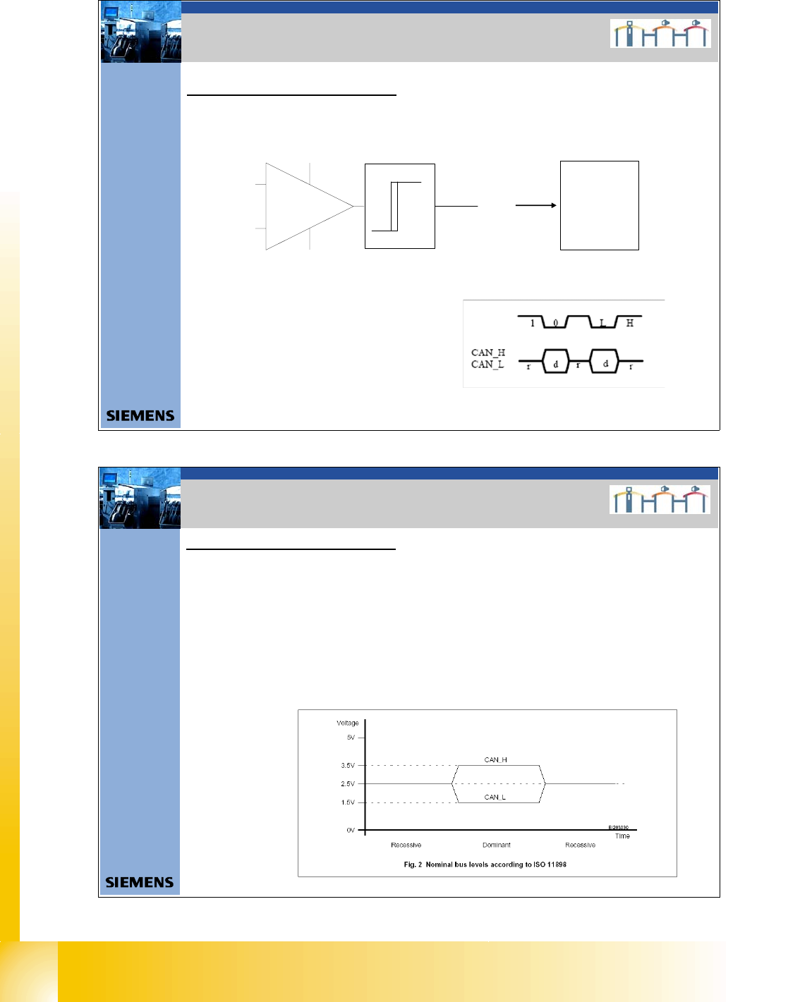
3. Check the recessive level
The CAN levels for CAN_H and CAN_ L differentiate between recessive and dominant levels.
This two levels will convert into a TTL level, for the CAN Processor. The RxD Signal has the
same phase such as the CAN_L Signal.
3. Checking the CAN BUS voltage
level
CAN_L
CAN_H
RxD
TTL Pegel
(Level)
16bit Can
processor
TQM
module
RxD
Naming convention for the CAN Signals
CAN_H : Recessive Signal (r)
Logic 1 (1)
High (H)
CAN_L: dominate Signal (d)
Logic 0 (0)
Low (L)
20Datum06/2008 Version 03 CAN Bus Workshop Mathias Michel
SIPLACE Campus
Automation and Drives
3. Messung der Spannungspegel
3. Check the recessive level
The recessive level (when CAN bus is idle i.e. there is no data transmission) can be measured statically,
with a voltammeter. Make sure no telegrams are sent during the measurement procedure. This means that
measurement may only be performed when the machine is not in operation.
Recessive Pegel = Logic „1“
Attention: Switch ON the machine and wait, so that are no communication on the CAN Bus!
Measure between GND and Pin 3 and GND and Pin 6).
Voltage value: 2.5 +/- 0,3V for CAN_H
2.5 +/-0,3V for CAN_L
3. Checking the CAN BUS voltage
level
1 - 13
Student Guide CAN BUS Workshop
Edition 06/2008 3 CAN BUS
13
21Datum06/2008 Version 03 CAN Bus Worksh op Mathias Michel
SIPLACE Campus
Automation and Drives
3. Messung der Spannungspegel
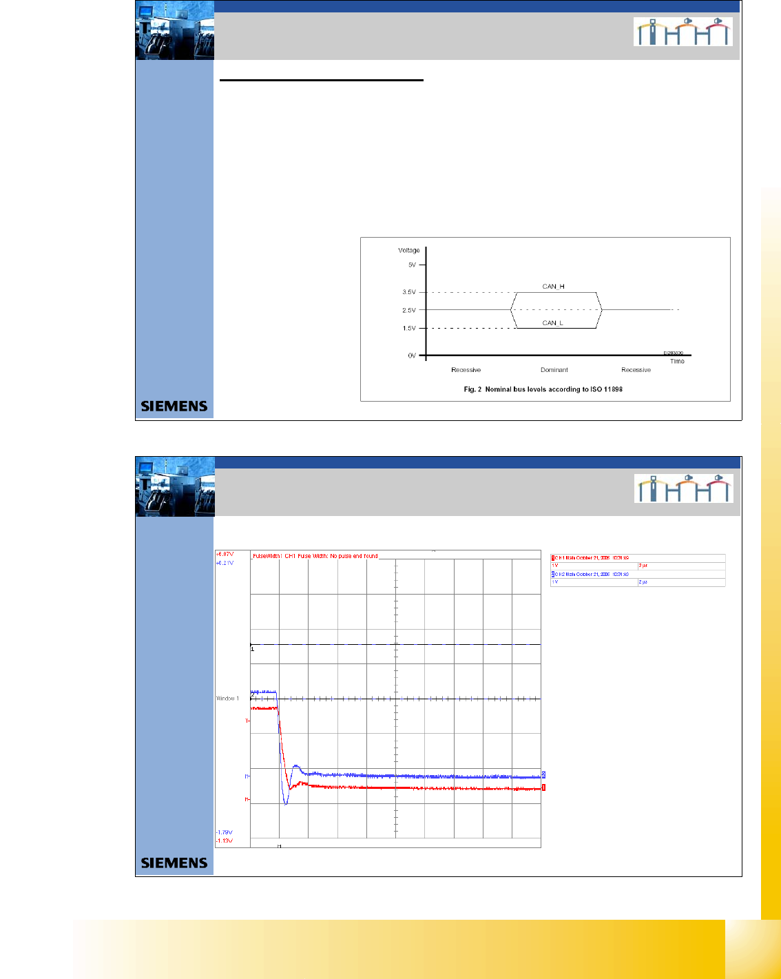
4. Check the dominant level
Dominant Level = Logic „0“
You need an oscilloscope to measure the dominant level.
To minimize the extent to which the measurement system influences the CAN signals, keep the
measurement line as short as possible.
- Connect the CAN Test Box to the service plug of the COM unit.
- Connect the oscilloscope to the BNC connectors CAN_H and CAN_L.
- Switch ON the machine
- To simulate CAN bus communication, you can start a version query in Sitest or Caccia.
- You can now check the signal voltage levels on the oscilloscope.
You should receive a value of 3.5V ( 2.75 - 4.5V) for CAN_H and of 1.5V (2.0 - 1.0V) for CAN_L
Voltage value:
CAN_H 3.5V ( 2.75 – 4.5V);
CAN_L 1.5V (2.0 – 1.0V)
3. Checking the CAN BUS voltage
level
22Datum06/2008 Version 03 CAN Bus Workshop Mathias Michel
SIPLACE Campus
Automation and Drives
3. Beispiele für mögliche Fehlerquellen
Short circuit between CAN High – Signal and GND
CAN High - Level
CAN Low - Level
3. Example for CAN BUS Errors

1 - 14
Student Guide CAN BUS Workshop
3 CAN BUS Edition 06/2008
14
23Datum06/2008 Version 03 CAN Bus Workshop Mathias Michel
SIPLACE Campus
Automation and Drives
3. Beispiele für mögliche Fehlerquellen
Short circuit between CAN High – Signal and CAN Low - Signal
CAN High - Level
CAN Low - Level
3. Example for CAN BUS Errors
24Datum06/2008 Version 03 CAN Bus Workshop Mathias Michel
SIPLACE Campus
Automation and Drives
3. Beispiele für mögliche Fehlerquellen
Short circuit between CAN Low – Signal and GND
CAN High - Level
CAN Low - Level
3. Example for CAN BUS Errors