CAN Bus Workshop_Version 03__06-2008_EN.pdf - 第88页
1 - 26 S tudent Gu ide CAN BUS Wor kshop 3 CAN BU S Editio n 06/200 8 26 46 Da tum06/2 0 08 Versi o n 03 CAN Bus Works hop Ma t hia s M ic he l SIPL ACE Ca mp us Automation a nd Drives 4. CAN B us St ru cture S iplace D4…
1 - 25
Student Guide CAN BUS Workshop
Edition 06/2008 3 CAN BUS
25
44Datum06/2008 Version 03 CAN Bus Workshop Mathias Michel
SIPLACE Campus
Automation and Drives
4. CAN Bus Structure Siplace D2
CAN
I/O Module
Sector 2
CAN Interface
1 MBit/s
CAN_ High
CAN_ L ow
120 Ohm
Compo nent tab le 1Compo nent tab le 2
Gant ry He ad D istri but
Gant ry 2
TQM
CAN_High
CAN_Low
CAN Bus 1 (1 Mbit/s)
Sub CA N Bus 2 (1MBbit/s)
C omponen t tabl e and
Ta pe cutter
Axis unit
Transport
control unit
Micr o BOX P C
(Machine controller)
Gantry Head Dis tributor
Ga nt ry 1
TQM
CAN_High
CAN_Low
CAN_Hi gh
CAN_Low
CAN_Hi gh
CAN_Low
Com. uni t
Tape cutter
Location 1
Tape cutter
Location 2
Com. unit
CAN Bus Terminator
Co mpon ent tabl e 1
CAN Bus Terminator
Component table 2
120 Ohm120 Ohm
12 0 O h m
12 0 O h m
Relay
contact K1
Re la y
contact K1
X 11p a
Micr o BOX P C
(Machine controller)
X1 2pa
CAN Bus 2 (1Mbit/s)
CAN_Hi gh
CAN_Low
120 Ohm
45Datum06/2008 Version 03 CAN Bus Workshop Mathias Michel
SIPLACE Campus
Automation and Drives
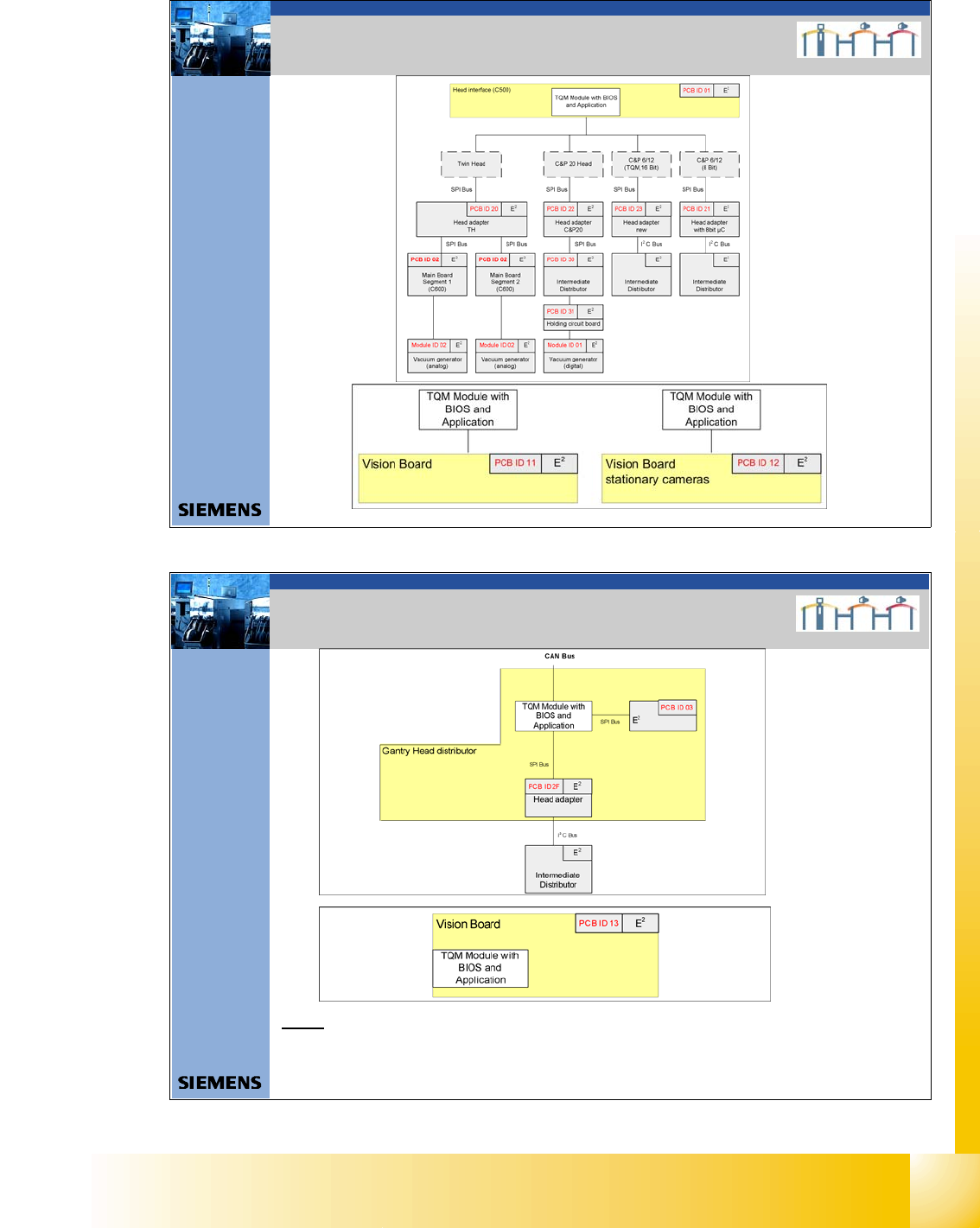
4. CAN Bus Structure Siplace D4
M
C
M
i
c
r
o
B
O
X
P
C
(
M
a
c
h
i
n
e
c
o
n
t
r
o
l
l
e
r
)
I
n
p
u
t
H
o
o
d
s
X
1
1
p
a
T
r
a
n
s
p
o
r
t
C
o
n
t
r
o
l
u
n
i
t
T
a
p
e
c
u
t
t
e
r
4
A
x
i
s
u
n
i
t
1
/
4
P
A
1
C
A
N
I
/
O
M
o
d
u
l
e
S
e
c
t
o
r
4
X
1
2
p
a
C
A
N
-
I
n
t
e
r
f
a
c
e
5
0
0
k
b
i
t
/
s
X
2
3
d
a
X
2
3
a
a
D
i
s
t
r
i
b
u
t
o
r
S
e
c
t
o
r
1
R
e
l
a
y
K
1
C
A
N
T
e
r
m
i
n
a
t
o
r
(
5
0
0
k
b
i
t
/
s
)
C
o
m
p
o
n
e
n
t
t
a
b
l
e
1
C
A
N
T
e
r
m
i
n
a
t
o
r
X
3
q
e
X
3
0
_
1
t
q
X
3
0
_
2
t
q
X
2
2
a
o
X
2
2
a
o
X
4
q
e
X
5
q
e
X
4
d
h
X
4
d
h
X
4
a
h
X
4
a
h
X
1
q
d
X
1
a
f
X
1
5
a
v
X
2
3
c
a
A
x
i
s
u
n
i
t
2
/
3
P
A
2
X
3
0
_
1
s
q
X
3
0
_
2
s
q
D
i
s
t
r
i
b
u
t
o
r
S
e
c
t
o
r
2
X
3
r
e
X
5
r
e
X
4
r
e
X
2
3
b
a
T
a
p
e
c
u
t
t
e
r
2
T
a
p
e
c
u
t
t
e
r
3
X
4
b
h
X
4
b
h
X
4
c
h
X
4
c
h
D
i
s
t
r
i
b
u
t
o
r
S
e
c
t
o
r
4
C
o
m
p
o
n
e
n
t
t
a
b
l
e
4
C
A
N
T
e
r
m
i
n
a
t
o
r
X
1
5
d
v
D
i
s
t
r
i
b
u
t
o
r
S
e
c
t
o
r
4
R
e
l
a
y
K
1
X
1
q
f
X
2
q
f
C
A
N
T
e
r
m
i
n
a
t
o
r
(
5
0
0
k
b
i
t
/
s
)
D-Series
D4-Machine
CAN Bus 1
PA1
CAN Bus 2
PA 2
C
A
N
-
B
u
s
-
B
a
u
d
r
a
t
e
:
1
M
b
i
t
/
s
5
0
0
k
b
i
t
/
s
R
e
l
a
y
K
1
C
A
N
T
e
r
m
i
n
a
t
o
r
(
5
0
0
k
b
i
t
/
s
)
C
o
m
p
o
n
e
n
t
t
a
b
l
e
3
C
A
N
T
e
r
m
i
n
a
t
o
r
X
1
r
d
X
1
c
f
X
1
5
c
v
D
i
s
t
r
i
b
u
t
o
r
S
e
c
t
o
r
3
C
o
m
p
o
n
e
n
t
t
a
b
l
e
2
C
A
N
T
e
r
m
i
n
a
t
o
r
X
1
5
b
v
D
i
s
t
r
i
b
u
t
o
r
S
e
c
t
o
r
2
R
e
l
a
y
K
1
X
1
r
f
X
2
r
f
C
A
N
T
e
r
m
i
n
a
t
o
r
(
5
0
0
k
b
i
t
/
s
)
Trailing distributor
Gantry 1
Gantry Head distributor
Gantry 1
CAN Terminator
(1MB it /s)
T
a
p
e
c
u
t
t
e
r
1
X11pa2
Service-
conn ector
X12pa2
Service-
connector
Trailing distributor
Gantry 4
Gantry Head distributor
Gantry 4
CAN Terminator
(1MBit/s)
Tra ilin g dis trib u to r
Gantry 3
Gantry Head distributor
Gantry 3
CAN Terminator
(1MBit/s)
Trailing distributor
Gantry 2
Gantry Head distributor
Gantry 2
CAN Terminator
(1MBit/s)
CAN I/O
Modul e
Sector 2
CAN Interface
500 kbit/s
1 - 26
Student Guide CAN BUS Workshop
3 CAN BUS Edition 06/2008
26
46Datum06/2008 Version 03 CAN Bus Workshop Mathias Michel
SIPLACE Campus
Automation and Drives
4. CAN Bus Structure Siplace D4
Component Table 1Component Table 4
Gantry head distributer
Gantry 4
TQM
CA N_High
CAN_Low
Machine CAN Bus
1 Mbit/s
CAN Bus for
Component table and
tape cutter 500 kbit/s
Axis u nit 1/4
PA 1
Transport
control unit
Micro BOX PC
(Machine controller)
Gantry head dis tributer
Gantry 1
TQM
CAN_Hig h
CAN_Low
CAN
I/O module
sector 4
CAN Interface
500 KBit/s
CAN_ Hig h
CAN_L ow
CAN_Hig h
CAN_Low
Com. unit
Tape cutter
Location 1
Tape cutter
Location 4
Com. unit
CAN Bus
Terminator
Comp.table 1
CAN Bus
Terminator
Comp.ta ble 4
120 O hm120 Ohm
12 0 Oh m
12 0 Oh m
Relays
conta ct K1
Relays
co nt act K 1
47Dat um06/2008 Version 03 CAN Bus Workshop Mathias Michel
SIPLACE Campus
Automation and Drives
Note:
For more information please see chapter communication and control in SG CAN
Bus Workshop, SG X-Serie or CACCIA manual.
5. One Wire Bus
5. One Wire Bus
One Wire Bus Siplace
HF-machine X-Series machine
Version 1
- i ntegrated in the CAN cable
- 24V power supply for NC,
in the CAN c able
Version 2
- integrated in the CAN cable
- 24V power supply from the
Docking unit (add. cable)
- R etrofi t kit number
( 00194610-01)
- TI 2005-08E03 CAN I/O
Module Version 02
Version 1
- One W ire Bus integ rated
i n CAT 5 cable
- 24V power supply for NC,
from th e Docking unit via
1-Wire CAT5 distrib utor
Version 2
- One Wire Bus monitor only
the te mpera tur sensors on
the head plate (CAN nod e)
- one C AT 5 cable goes directly
to the trailling interface .
Version 3
- new board on the I /O module
- Interfa ce 1-W ire C AN 2, for the
option WPC 4 with SW60 5
Version 3
- integrated 1-Wire CAT 5
Interfac e into the C AN I /O
Module (Version 03)
1 - 27
Student Guide CAN BUS Workshop
Edition 06/2008 3 CAN BUS
27
48Datum06/2008 Version 03 CAN Bus Workshop Mathias Michel
SIPLACE Campus
Automation and Drives
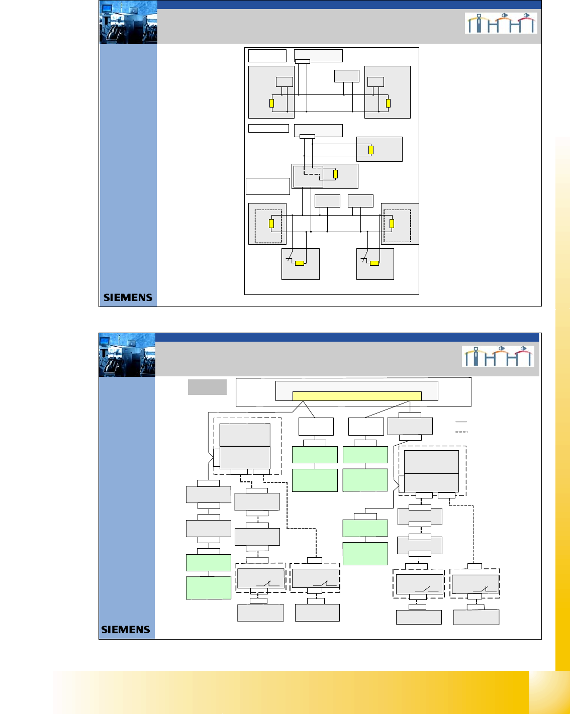
6. LP Kennung X-Series machine
6. Board type recognition
49Datum06/2008 Version 03 CAN Bus Workshop Mathias Michel
SIPLACE Campus
Automation and Drives
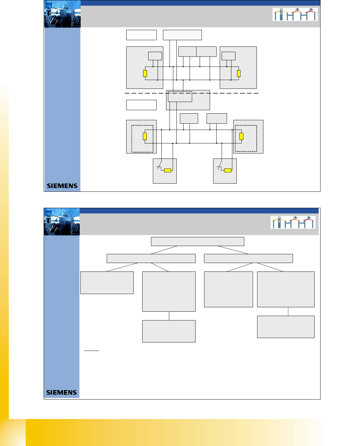
6. LP Kennung D-Series machine
6. Board type recognition
Note:
For more information please see chapter communication and control in SG CAN
Bus Workshop, SG X-Serie or CACCIA manual.