CAN Bus Workshop_Version 03__06-2008_EN.pdf - 第172页
1 Caccia Student Guide CACCIA Manual Issue 04/2007 EN 80 Fig. 1 - 55 NC control board only at the 20 C&P head nozzle changer Fig. 1 - 56 Posit ion of temperature sensors on the head plate Fig. 1 - 57 T emperature sen…
CACCIA Manual 1 Caccia Student Guide
Issue 04/2007 EN
79
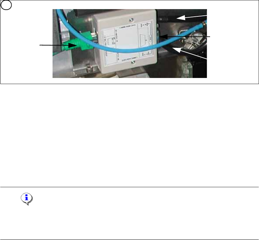
Fig. 1 - 54 1 wire hub for NC (03041473-02)
Note
In future we don‘t have the switch for the location code (only HF). The location code for the noz-
zlechanger will be realized via hardware, directly in the connector on the location (X112 / X122 /
X132 / X142) at HF and Siplace X. 1
(1) Input CAT 5 cable from the CAT 5
splitter
(2) SUB-D connector for option (query reject con-
tainer)
(3) Connection NC 1 (4) Connection NC 2
on the right side display (2 LED‘s) for NC C&P6/12 Light barrier NC open/closed and Valve NC
open/closed for each row
on the left side two LED‘s directly on the connector
yellow LED: Reject box components connected
green LED: Reject box nozzles connected
4
1
2
3
4

1 Caccia Student Guide CACCIA Manual
Issue 04/2007 EN
80
Fig. 1 - 55 NC control board only at the 20 C&P head nozzle changer
Fig. 1 - 56 Position of temperature sensors on the head plate
Fig. 1 - 57 Temperature sensors / gantry recognition
Display (2 LED‘s) for NC C&P20 (The LED‘s are invisible because there is a cover under the NC)
Light barrier NC open/closed and Valve NC open/closed
5. Temperature sensor on the PCB cam-
era
(6) Temperature sensor/ EEPROM gantry recog-
nition
7. Temperature sensor on the PCB cam-
era
(8) Temperature sensor/ EEPROM gantry recog-
nition
5
Connection to 1 wire
hub for NC
1
2
6
6
21
CACCIA Manual 1 Caccia Student Guide
Issue 04/2007 EN
81
Note
The temperatursensor are connected directly on the connector X20 or X21 on the Head interface
C500. You can use one of the two connectors. 1
1.11.2 Function Control and Troubleshooting for Service Work
This section provides an overview of how to assign the one wire bus subsystems to the relevant
hardware assemblies, enabling a structured approach to service work.
1.11.2.1 Subsystem Query in PA1
– Connect the service laptop to the machine CAN bus at PA1.
Make sure that the cable is connected to channel 1 for PA1 and that, at least the transmitter is
connected to channel 2 of the Kvaser card.
– Start the "CACCIA" software and check the machine configuration with Caccia.
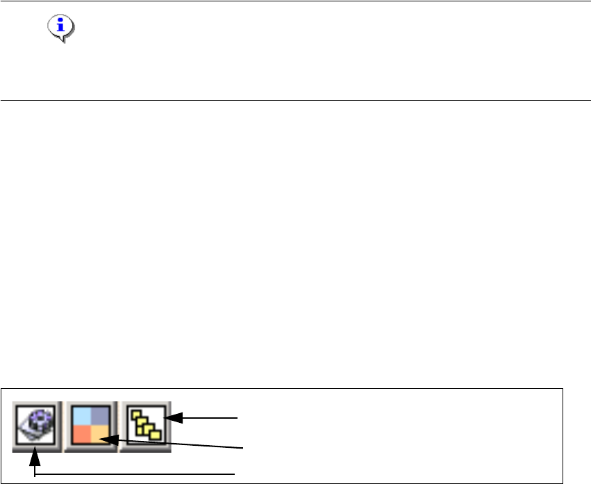
– Doubleclick to open the subsystem control center.
Fig. 1 - 58 Icons: properties, machine configuration, subsystem control center
Subsystem control center
Machine configuration window
Properties (settings, restart Kvaser card)