CAN Bus Workshop_Version 03__06-2008_EN.pdf - 第72页
1 - 10 S tudent Gu ide CAN BUS Wor kshop 3 CAN BU S Editio n 06/200 8 10 15 Datum 06/2008 Version 0 3 CAN Bu s Wo r ksh op Mathias M ichel SIPL ACE Camp us A utomation a nd Dri ves 3. Ausw irkung der Abschl ußwiderstände…
1 - 9
Student Guide CAN BUS Workshop
Edition 06/2008 3 CAN BUS
9
13Datum06/2008 Version 03 CAN Bus Workshop Mathias Michel
SIPLACE Campus
Automation and Drives
3. Physikalische Überprüfung des CAN Bus
Signals on the different connectors
Differences:
Siplace HF: - Take out 24V from the CAN Bus
Retrofit kit number(00194610-01)
- TI 2005-08E03 CAN I/O Module Version 02
Siplace X: - Changing the 24 V power supply
- One Wire with CAT5 cable (00194705-01)
- One Wire (CAT 5) control only Temperatur
sensors
• CAN_INT - not used (+5V/ min. 4V)
• Power Fail - to storage the head specific data
(+5V/ min. 4V)
• CAN RESET - not used on HF and X machine
(+5V/ min. 4V)
• CAN HIGH - 2,5 +/- 0,3 V recessive Level
(When there is no communication on the Can Bus)
• CAN LOW - 2,5 +/- 0,3 V recessive Level
(When there is no communication on the Can Bus)
• CAN GND - Ground Can Bus
• Vcc 24V - was the 24V for the nozzle changer before.
• One wire - Only on the HF machine in the
CAN Bus cable
3. Checking the physical function
of the CAN BUS
9- pol Sub D
2 3 4 5
7 8 9
1
6
2
3
4
5
1
10 - Pin connector
7
8
9
10
6
2
3
4POWER_FAIL
5
CAN_INIT
6
CAN_GND
CAN_GND
7 CAN_HIGH
8
CAN_LOW
CAN-RESET
9 Vcc One_Wire (+24 V)
ONE_Wire
1
(+5V ) LOW_ ACTIVE
3
5
7POWER_FAIL
9
CAN_INIT
2
CAN_GND
CAN_GND
4CAN_HIGH
6
CAN_LOW
CAN-RESET
8 Vcc One_Wire (+24 V)
10
ON E_Wire
1
NC
(+5V) LOW_ ACTIVE
1 One_Wire
2 CAN_GND
3 CAN_LOW
4 CAN_HIGH
5 CAN_GND
6 CAN_RESET
7 Power_FAIL
8 Vcc_One_Wir e (+24V)
9 CAN_IN IT
10 NC
1 2 3 4 5 6 7 8 9 10
10 Wi re flat cable
Description Flat cable
Description 10 pi n co nnectorDescription 9 sub D co nn ector
14Datum06/2008 Version 03 CAN Bus Workshop Mathias Michel
SIPLACE Campus
Automation and Drives
1. Check the terminating resistors
Attention: To measure the terminating resistors you have to SWITCH OFF the machine!
To avoid reflection in the CAN lines, a 120 Ohm terminating resistor must be placed at each
end of the CAN bus wire, between CAN_H and CAN_L.
A correctly closed CAN bus will have a resistance value of 60 Ohm.
An additional terminating resistor reduces the overall resistance to 40 Ohm. (1/Rges.= 1/R1+1/R2+.....)
If the resistors are not placed at the end points, the CAN lines will experience reflections.
The effect of incorrect terminating resistors can be seen in the appropriate diagram in this .ppt.
Measure: Between Pin 2 and 7
Nominal value: 60 O
For the positions of the terminating resistors,
refer to Chapter CAN Bus Operation Diagrams in the manual CAN Test Box
3. Überprüfung der Abschlußwiderstände
3. Checking the terminating resistors
1 - 10
Student Guide CAN BUS Workshop
3 CAN BUS Edition 06/2008
10
15Datum06/2008 Version 03 CAN Bus Workshop Mathias Michel
SIPLACE Campus
Automation and Drives
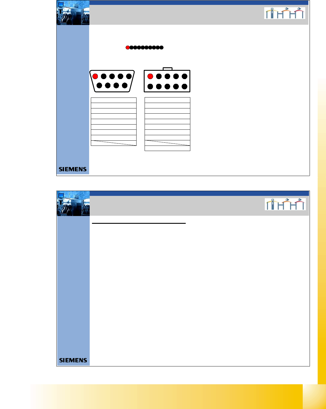
3. Auswirkung der Abschlußwiderstände
Terminating Resistors 60 Ohm Æ OK
CAN High - level approx. 1,5V
CAN Low – Level approx. 1,5 V
3. Effect terminating resistors
16Datum06/2008 Version 03 CAN Bus Workshop Mathias Michel
SIPLACE Campus
Automation and Drives
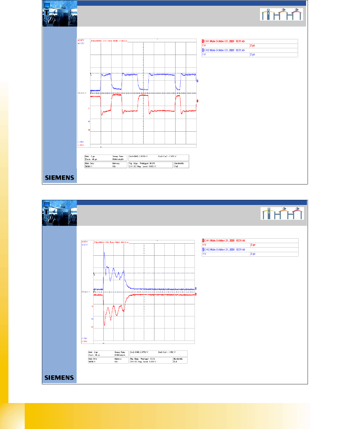
3. Auswirkung falscher Abschlußwiderstände
Terminating Resistors 120 Ohm
CAN High - Level
CAN Low - Level
3. Effect wrong terminating resistors
1 - 11
Student Guide CAN BUS Workshop
Edition 06/2008 3 CAN BUS
11
17Datum06/2008 Version 03 CAN Bus Workshop Mathias Michel
SIPLACE Campus
Automation and Drives
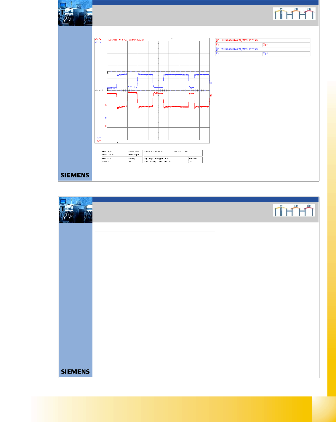
Terminating Resistors 40 Ohm
CAN High - Level < 1,5 V
CAN Low – Level < 1,5 V
3. Effect wrong terminating resistors
3. Auswirkung falscher Abschlußwiderstände
18Datum06/2008 Version 03 CAN Bus Workshop Mathias Michel
SIPLACE Campus
Automation and Drives
2. Check the Power fail, CAN init, -reset signals
Although the CAN Init and CAN Reset signals are not used in some cases (machine-specific),
they still have a voltage level of 5V (min.4,0V)
The sporadic drop in voltage or a short circuit to other signals could lead to logical faults in the
CAN bus system (e.g. CAN timeout).
Should problems with the CAN bus occur, always check the signal voltage levels
Note:
In some machines, the wires for CAN init,CAN reset and power fail may have been removed
from the CAN bus cable at the COM assembly. In this case, the easiest way to check
voltages levels is at the RS232 bridge, in the main and sub distributors.
3. Überprüfung der Spannungen
(CAN init,-reset,Power fail)
3. Checking the Power Fail, CAN Init,-Reset
Signals