CAN Bus Workshop_Version 03__06-2008_EN.pdf - 第40页
1 - 14 S tudent Gu ide CAN BUS Wor kshop 2 Commun icatio n and C ontrol Editio n 06/200 8 14 2.2.5 CAN Bus Concept SiplaceX 2 The placem ent mac hine SIPLAC E X2 use s a bu s syst em with 1 Mbit/ s trans missio n rate. T…
1 - 13
Student Guide CAN BUS Workshop
Edition 06/2008 2 Communication and Control
13
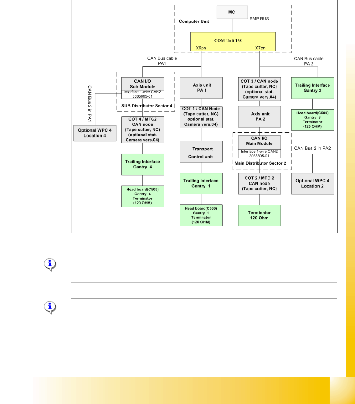
2.2.4 CAN Bus Concept SiplaceX3
The placement machine SIPLACE X3 uses a bus system with 1 Mbit/s transmission rate.The CAN
Bus system begin at the Communication board and is split in 2 path. Every path is terminated by
a 120 ohm terminator on the head board at the individual placement head.
.
Fig. 2.2 - 11 CAN Bus overview Siplace X3
Note: When the Twin head is mounted, the switch for the terminator on the head board (C500)
have to be OFF. 2
Note: From SW 605 the WPC4 will be offered as an option for the X2 and X3. This option requires
thenew "Interface 1-Wire CAN2". The WPC is then controlled via the CAN2.When the Twin head
is mounted
1 - 14
Student Guide CAN BUS Workshop
2 Communication and Control Edition 06/2008
14
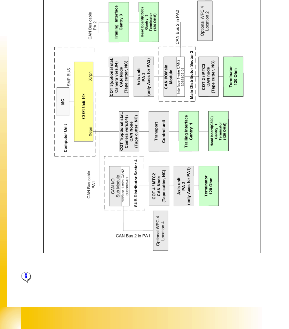
2.2.5 CAN Bus Concept SiplaceX2
The placement machine SIPLACE X2 uses a bus system with 1 Mbit/s transmission rate.The
CAN: Bus system begin at the Communication board and is split in 2 path. Every path is termi-
nated by a 120 ohm terminator on the head board at the individual placement head
Fig. 2.2 - 12 CAN Bus overview Siplace X2
Note: When the Twin head is mounted, the switch for the terminator on the head board (C500)
have to be OFF. 2
1 - 15
Student Guide CAN BUS Workshop
Edition 06/2008 2 Communication and Control
15
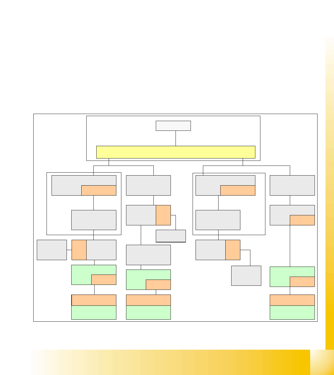
2.2.6 One Wire Bus
2.2.6.1 Siplace HF/HF3
The placement machine SIPLACE HF/HF3 uses with the Software 505 an additional bus system,
which are integrated into the CAN Bus cable --> One Wire Bus.
With the Siplace X-machine the One Wire Bus is integreted in a separate CAT5 cabel, which start
from the Main- and Subdistributor up to the trailling interface. Independent of the circuit diagram,
on the Main- and Subdistributor are installed the control unit of the one wire system. A kind of
switch are located on the other units which required the one wire system (see figure below). This
switch open and close the communication path.
Controlled components with the ONE Wire Bus:
– Nozzle changer of the C&P heads
– Temperature sensors
– Gantry recognition (CFK02, CFK04, CFK06)
– Option Reject Box
Fig. 2.2 - 13 General overview CAN-Bus with One Wire Siplace HF3
SMP BUS
MC
MC
Axis unit
PA 1
CAN Bus cable
Computer Unit
CAN E/
A
Modu
l
Sektor
4
CAN E/
A
Modu
l
Sektor
4
CAN E/
A
CAN I/O
SUB Modul
Sektor 4
COT 1
Tape cutter
SUB Distributor Sector 4
Main Distributor Sector 2
C
O
M
U
n
i
t
x
6
p
n
x
7
p
n
CAN Bus cable
One Wire
"Control unit"
One Wire
"Switch"
CAN Bus cable
with One Wire
COT 4
Tape cutter
Vision
Control unit
Sector 4
Trailing
cable-
Interface
Gantry 4
One Wire
"Switch"
Temperature sensor
Gantry recognition
One Wire
"Head interface"
Temperature sensor
Gantry recognition
One Wire
"Head interface"
Axis unit
PA 2
COT 3
Tape cutter
One Wire
Hub
One Wire
"Switch"
Temperature sensor
Gantry recognition
One Wire
"Head interface"
CAN I/O
Main Modul
Sector 2
One Wire
"Control unit"
CAN Bus cable
with One Wire
Transport
Control
unit
Nozzle
changer A/B
COT 2 / MTC
Tape cutter
Vision
Control unit
Sector 2
Nozzle
changer A/B
One Wire
Hub
One Wire
Hub
Nozzle
changer A/B
One Wire
Hub
Trailing
cable-
Interface
Gantry 1
Trailing
cable-
Interface
Gantry 3