CAN Bus Workshop_Version 03__06-2008_EN.pdf - 第193页
CACCIA Manual 1 Caccia Student Guide Issue 04/2007 EN 101 1.12.2.2 Read and write the Board type ID with CAN commands – Switch off the machine. – Connect the service laptop to the machine CAN bus at P A1 and/or P A2. Mak…
1 Caccia Student Guide CACCIA Manual
Issue 04/2007 EN
100
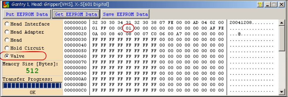
Attention: The vacuum generator digital (C&P20) and thevacuum generator analog (Twin head)
don‘t have a board type ID. In the memory space on the EEPROM stays 00.
Important: Both vacuum generators will be recognized via a device number.
The device number is saved in the memory space 14 on the EEPROM.
Device number ID 01 vacuum generator digital
Device number ID 02 vacuum generator analog
Fig. 1 - 74 Device number vacuum generator digital C&P20
CACCIA Manual 1 Caccia Student Guide
Issue 04/2007 EN
101
1.12.2.2 Read and write the Board type ID with CAN commands
– Switch off the machine.
– Connect the service laptop to the machine CAN bus at PA1 and/or PA2.
Make sure that the cable is connected to channel 1 for PA1 and that, at least the transmitter is
connected to channel 2 of the Kvaser card.
– Switch on the machine
– Start the "CACCIA" software and check the machine configuration with Caccia.
– Doubleclick to open the subsystem control center.
Fig. 1 - 75 Icons: properties, machine configuration, subsystem control center
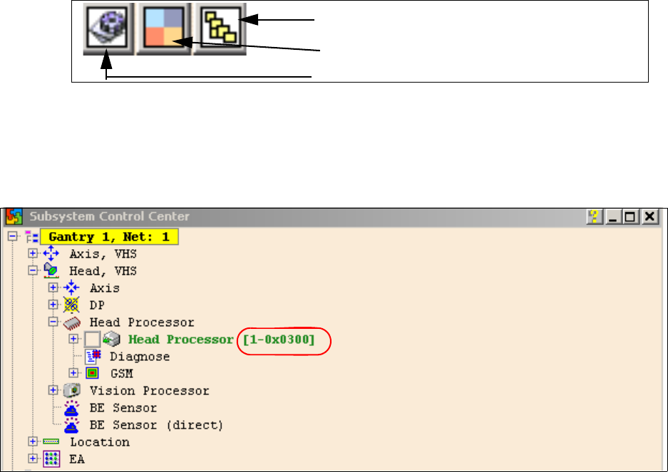
– Click on the "Get Versions" button.
The system will display all available subsystems with their firmware versions and CAN IDs.
Fig. 1 - 76
– Look for the right CAN ID in the Subsystem Control Center depending on the error and use this
CAN ID to work in the network windows.
– This means, for check the Head interface, Head adapter and Intermediate distributor use the
CAN ID 300 for Gantry 1 or 308 for Gantry 2 and so on.
Subsystem control center
Machine configuration window
Properties (settings, restart Kvaser card)

1 Caccia Student Guide CACCIA Manual
Issue 04/2007 EN
102
Note
Please use always the ID‘s, which you get if you press the Button " GET VERSION or ACTIVATE
ID‘s" in the Subsystem Control window.
e.g. Head Processor: Portal 1 --> 300
Portal 2 --> 308
Portal 3 --> 310
Portal 4 --> 318
Exception: If you don‘t received a message from a subsystem, so you can try to work with "Stan-
dard ID‘s" e.g.Head processor: Gantry 1 --> 304 / Gantry 2 --> 30C / Gantry 3 --> 314 / Gantry 4
--> 31C 1
– If you want to write Board type ID‘s with CAN commands, it is necessary, that the TQM module
is running with the BIOS only!
– At first, carry out the BIOS download on the TQM module, thus you are sure that the TQM mod-
ule is running in the BIOS only.
– Open the network 1 for PA 1 and network 2 to for PA 2.
– With the right CAN ID and the CAN commands you can write the correct ID in the EEPROM.