CAN Bus Workshop_Version 03__06-2008_EN.pdf - 第188页
1 Caccia Student Guide CACCIA Manual Issue 04/2007 EN 96 1.12.2 Check and write of the board type ID‘s on the EEPROM With the aid of the CACCIA tool you can check the boar d type ID‘s on each board. Y ou can use CAN Bus …
CACCIA Manual 1 Caccia Student Guide
Issue 04/2007 EN
95
Note
At the moment, there is no check on the board type ID‘s from the vision boards (gantry 1-4),
illumination board stationary Cameras (Location 2/4) and the Vacuumsensor holding circuit board
C&P20. 1
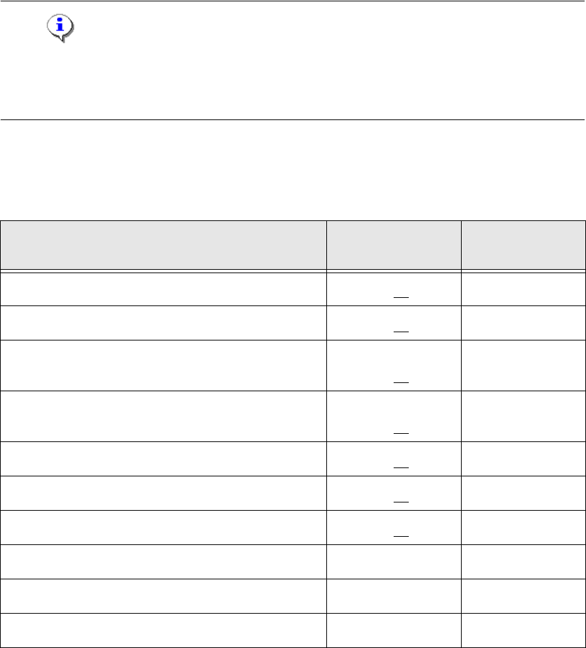
1.12.1.4 PCB‘s with board type ID‘s
PCB‘s with ID
board type
recognition (ID)
Hardware version
of the PCB‘s
Head interface (C500)
0x01 -05
Head adapter C&P20
0x22 -04
Head adapter C&P6/12 (with 16 bit processor TQM on
the head interface)
0x23 -02
Head adapter C&P6/12 (with 8 bit processor on the
head adapter)
0x21 -??
Head adapter Twin Head
0x20 -03
Intermediate distributer C&P20
0x30 -06
Main board Twin Head (C600)
0x02 -08
Vision board
0x11 -??
Illumination board (stationary Cameras)
0x12 -??
Vacuumsensor holding circuit board
0x31 -02
Tab. 1 - 21 board type ID‘s
1 Caccia Student Guide CACCIA Manual
Issue 04/2007 EN
96
1.12.2 Check and write of the board type ID‘s on the EEPROM
With the aid of the CACCIA tool you can check the board type ID‘s on each board.
You can use CAN Bus commands to read the board type ID‘s or open the corresponding menue
to read the memory of the EEPROM. When one or more ID‘s are missing so you can write the
correct ID on the board.
At the moment it is necessary to use the correct ID‘s on the board which are installed on the gantry
(Head interface, - adapter, Intermediate distributor and main board). The other board type ID‘s are
not used at the moment.
Note
Direct CAN bus commands should only be used by specially trained and qualified service techni-
cans. 1
1.12.2.1 Read out the Board type ID via the menu Gripper
Note
When you want to be read out the board type ID‘s via the menu gripper, the BIOS and application-
software have to downloaded on the TQM module.
At the moment you can only read the ID‘s via the menu Gripper, to write the ID‘s on the EEPROM
you need CAN Bus commands. 1
– Switch off the machine.
– Connect the service laptop to the machine CAN bus at PA1 and/or PA2.
Make sure that the cable is connected to channel 1 for PA1 and that, at least the transmitter is
connected to channel 2 of the Kvaser card.
– Switch on the machine
– Start the "CACCIA" software and check the machine configuration with Caccia.
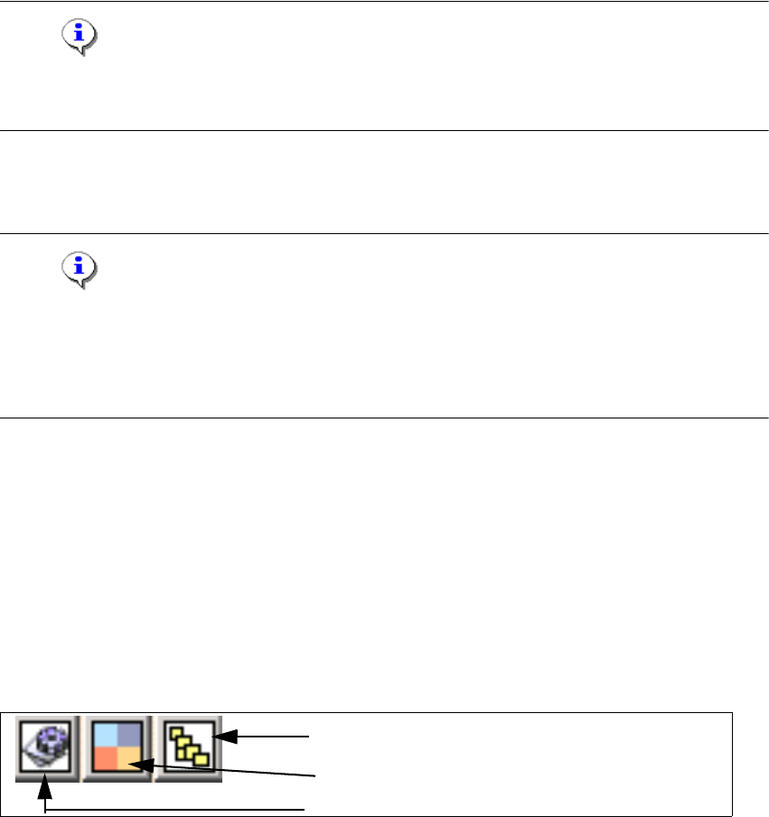
– Doubleclick to open the subsystem control center.
Fig. 1 - 67 Icons: properties, machine configuration, subsystem control center
Subsystem control center
Machine configuration window
Properties (settings, restart Kvaser card)
CACCIA Manual 1 Caccia Student Guide
Issue 04/2007 EN
97
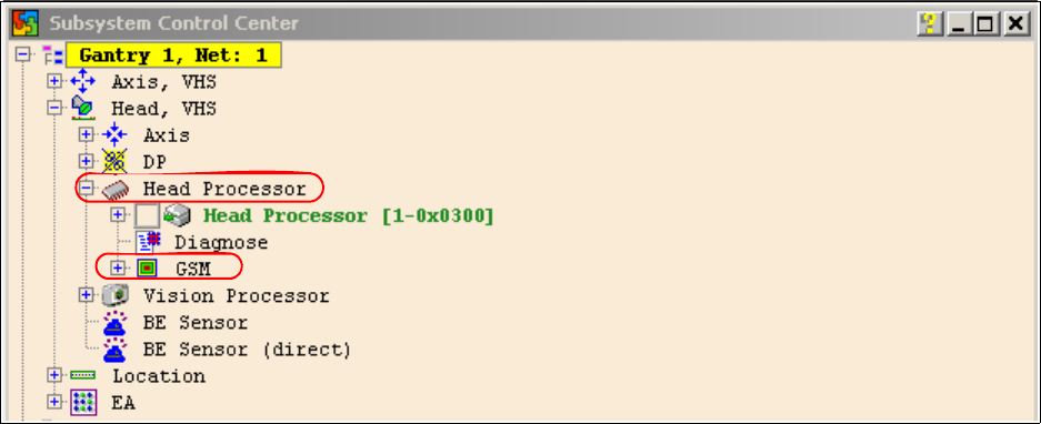
– Click on the "Get Versions" button.
The system will display all available subsystems with their firmware versions and CAN IDs.
– Choose the head processor according the gantry e.g. gantry 1
– Open the GSM - Folder
Fig. 1 - 68 Subsystem control center
– Doubleclick on Gripper and the following dialog appears.