CAN Bus Workshop_Version 03__06-2008_EN.pdf - 第83页
1 - 21 S tudent Guide CAN BUS W orkshop Edition 06/20 08 3 CAN B US 21 36 Dat um 06/2008 Versio n 0 3 CAN Bu s W o rkshop M at hi as M ichel SI PL ACE Ca m p u s Automati on and Driv es 4. CA N B us St r u ktu r S ipla c…
1 - 20
Student Guide CAN BUS Workshop
3 CAN BUS Edition 06/2008
20
34Dat um06/2008 Version 03 CAN Bus Workshop Mathias Michel
SIPLACE Campus
Automation and Drives
4. CAN Bus Struktur Siplace HF aktuell
4. Current CAN BUS structure
Siplace HF
SMP BUS
C
O
M
U
n
i
t
K
S
P
3
5
4
MC
CAN Bus cable 2
Computer Unit
For each Placementarea one CAN Bus!
* with SW 505 Gantry 2 is changed to gantry 3
new cable loop!
new circuit diagram!
Trailing cable-
Interface
Gan try 1
Transport
COT 1
Tap e cutter
Control unit
CAN Bus cable 1
CAN E/
AModu
l
Sektor
4
CAN E/
A
Modu
l
Sektor
4
CAN E/
AModu
l
Sektor
4
CAN I/O
SUB Module
Section 4
Vision
Control unit
SUB Distributor Section 4
Section 4
CO T 4 / M TC
Tape cutter
Vision
Section 2
CAN I/O
Main Module
Section 2
Main Distributor Section 2
Cont ro l unit
COT 2 / MTC
Tape cutter
Axis unit
PA 2
CO T 3
Tape cutter
Trailing cable-
Interface
Gantry 3*
x6pnx11pn
Head board(C5 00 )
Gantry 1
Ter mi nator
(120 OHM)
Head board(C500 )
Gantry 3*
Te rm inator
(120 OHM)
Terminator (120 OHM)
[near the trailingcable
interface ]
Terminator (120 OHM)
[nea r the trailingcable
interface]
- CAN Bus Structure with SW 505.xx
- Com unit KSP 354
- Universal cable
(label on the cable (0301xxxx-0x)
- one CAN Bus for each placement area.
35Datum06/2008 Version 03 CAN Bus Workshop Mathias Michel
SIPLACE Campus
Automation and Drives
4. CAN Bus Struktur Siplace HF/3 Aktuell
- CAN Bus Structure with SW 505.xx
- Com unit KSP 354
- Universal cable
(Label on the cable (0301xxxx-0x)
- one CAN Bus for each placement area.
SM P BU S
C
O
M
U
n
i
t
K
S
P
3
5
4
MC
CAN Bus cab le 2
Computer U nit
Trailing cable-
Interface
Gantry 4
Transport
COT 1
Tape cutter
Control unit
CAN Bus c abl e 1
CAN E/
A
Modu
l
Se ktor
4
CAN E/
A
Modu
lSektor
4
CAN E/
A
Modu
l
Se ktor
4
CAN I/O
SUB Module
Section 4
Vision
Control unit
SUB Distributor Section 4
Section 4
COT 4
Tape cutter
Vision
Section 2
CAN I/O
Main Module
Se ction 2
Main Distributor Section 2
Control unit
COT 2 / MTC
Tape cutter
Axis unit
PA 2
COT 3
Tape cutter
Trailing cable -
Interface
Gantry 3
x6pnx11pn
He ad boa rd( C50 0 )
Gantry 1
Terminator
(120 OHM )
Head board(C500)
Gantry 3
Ter mina tor
(120 OHM)
Terminator ( 12 0 OHM)
[near the trailingcable
interface]
Axis unit
PA 1
Head board(C500)
Gantr y 4
Terminator
(120 OHM)
Trailing cabl e-
Inter face
Gantry 1
4. Current CAN BUS structure
Siplace HF 3
1 - 21
Student Guide CAN BUS Workshop
Edition 06/2008 3 CAN BUS
21
36Datum06/2008 Version 03 CAN Bus Workshop Mathias Michel
SIPLACE Campus
Automation and Drives
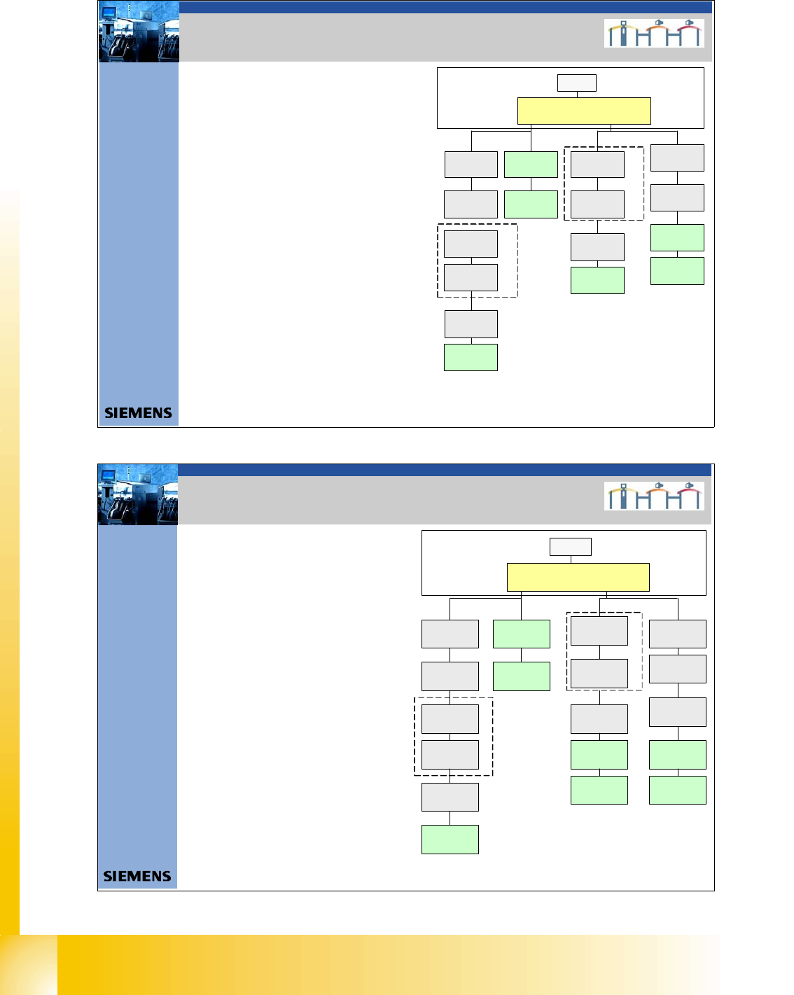
4. CAN Bus Struktur Siplace X2
4. CAN BUS structure Siplace X 2
- CAN Bus Structure with SW 605.xx
- Com unit KSP 168
- Universal cable (Label on the cable
0301xxxx-0x)
- one CAN Bus for each PA
-The stationary camera can
installed in location
1 or 3, depend on
the head configuration
-
- For new stationary cameras,
we don`t have the VCU in
sector 2 and 4. The CAN Bus
connectorisdirectlyon the
cameras.
- With this structure, the NC, sensors for the
reject boxes and the nozzle station are
controlled via CAN Bus again.
SMP BUS
Computer Unit
C
O
M
U
n
i
t
1
6
8
CAN Bus cable
PA1
X6pn
Trailing Interface
Gantry 1
Transport
Control unit
COT 1( opti onal s ta t.
Camera vers.04) /
CAN Node
(Tape cutter, NC)
CAN I/O
Sub Module
COT 4 / MTC2
CAN Node
(Tape cutter, NC)
SUB Di stributor Se c tor 4
Term inator
120 Ohm
Head board (C500)
Gantr y 1
Terminator
(120 OHM)
CAN Bus cable
PA 2
X7 p n
Main Distributor Sector 2
COT 3(optional stat.
Camera vers.04)
CAN Node
(Tape cutter, NC)
Axis unit
PA 2
(only Axes for PA 2)
CAN I /OMain
Module
COT 2 / MTC 2
CAN node
(Tape cutter, NC)
Trailing Inte rfa ce
Gantry 3
Terminator
120 Ohm
Head board (C500)
Gantry 3
Terminator
(120 OHM)
Axis unit
PA 2
(only Axes for PA1)
MC
Opti on al WPC 4
Location 4
CAN Bus 2 in PA1
Interface 1-wire CAN2
3065805 -01
Optional WPC 4
Location 2
Interfac e 1 -wire CAN2
3065805 - 01
CAN Bus 2 in PA2
37Datum06/2008 Version 03 CAN Bus Workshop Mathias Michel
SIPLACE Campus
Automation and Drives
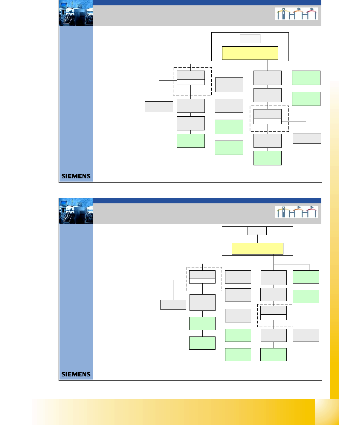
4.CAN Bus Struktur Siplace X3
4. CAN BUS structure Siplace X 3
- CAN Bus Structure with SW 605.xx
- Com unit KSP 168
- Universal cable (Label on the cable
0301xxxx-0x)
- one CAN Bus for each PA.
- For new stationary cameras,
we don`t have the VCU in
sector 2 and 4. The CAN Bus
connectorisdirectlyon the
cameras.
- The stationary camera can
installed in location 1, 4 or 3,
depend on the head
configuration .
SMP BUS
Computer Unit
C
O
M
U
n
i
t
1
6
8
CAN Bus cable
PA1
X6pn
Trailing Interface
Gantry 1
Transport
Control unit
Axi s unit
PA 1
SUB Distributor Sector 4
Tra iling Interface
Gantry 4
Head board (C500)
Gantry 4
Terminator
(120 OHM )
H ead bo ard (C500 )
Gantry 1
Terminator
(120 OH M)
CAN Bus cable
PA 2
X7pn
Main Distributor Sector 2
Axis unit
PA 2
COT 2 / MTC 2
CAN node
(Tape cutter, NC)
Terminator
120 Ohm
Trailing Interface
Gantry 3
Head board (C500)
Gantry 3
Terminator
(120 OHM)
MC
CO T 4 / MT C2
CAN node
(Tape cutter, NC)
(optional stat .
Ca mera vers.04)
COT 3 / CAN node
(Tape cutter, NC)
(optional stat .
Camera vers.04)
COT 1 / CAN Node
(Tape cutter, NC)
optional stat.
Camera vers.04)
CAN I/O
Sub Module
Interface 1-wire CAN2
3065 80 5 -0 1
CAN I/O
Main Module
Interfac e 1-wire CAN 2
30 65 805 -01
Optional WPC 4
Location 2
CAN Bus 2 in PA2
Optional WPC 4
Location 4
CAN Bus 2 in PA1
1 - 22
Student Guide CAN BUS Workshop
3 CAN BUS Edition 06/2008
22
38Datum06/2008 Version 03 CAN Bus Workshop Mathias Michel
SIPLACE Campus
Automation and Drives
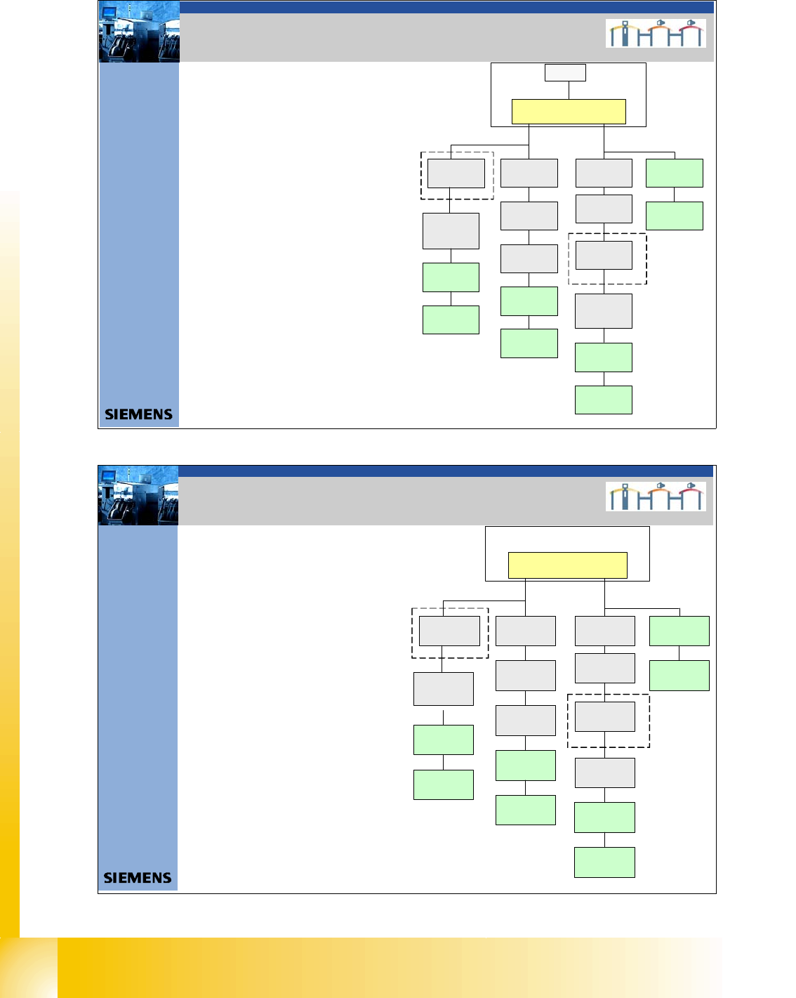
4. CAN Bus Struktur Siplace X4
4. CAN BUS structure Siplace X 4
- For new stationary cameras,
we don`t have the VCU in
sector 2 and 4. The CAN Bus
connector is directly on the
cameras
- The stationary cameras can
installed in location 1, 4 or 2,and 3,
depend on the head configuration.
- With this structure, the NC,
sensors for the reject boxes
and the nozzle station are
controlled via CAN Bus again.
SMP BUS
MC
MC
Computer Unit
C
O
M
U
n
i
t
1
6
8
CAN Bus cable
PA 1
X6pn
Trailing Interface
Gantry 1
Transport
Control unit
COT 1 / CAN node
(Tape cutter, NC)
optional stat.
Ca me ra ve rs.04)
Axis unit
PA 1
CAN I/O
Sub Module
SUB Distributor Sector 4
Trailing Inte rf ac e
Gantry 4
Head board (C500 )
Gantry 4
Terminator
(120 OHM )
Head board( C500)
Gantry 1
Terminator
(120 OHM)
CAN Bus cable
PA 2
X7pn
Main Distributor Sector 2
Axis unit
PA 2
CAN I/O
Main Module
COT 2 / MTC2
CAN node
(Tape cutter, NC)
(optiona l st at .
Camera vers.04)
Trailing Interface
Gantry 2
Trailing Interface
Gantry 3
Head board (C500)
Gantr y 2
Terminator
(120 OHM)
Head board (C500)
Gantry 3
Terminator
(120 OHM)
COT 3 / CAN node
(Tape cutter, NC)
(optional stat.
Camera vers.04)
COT 4 / MTC 2
CAN node
(Tape cutter, NC)
(optional stat.
Camera vers.04)
39Datum06/2008 Version 03 CAN Bus Workshop Mathias Michel
SIPLACE Campus
Automation and Drives
4. CAN Bus Struktur Siplace X4I
4. CAN BUS structure Siplace X 4
- For the new Siplace X4I and SW 701, we don`t
have an MC. One Box PC control the machine
and the Other PC is only for Siplace Vision.
- With this structure, the NC,
sensors for the reject boxes
and the nozzle station are
controlled via CAN Bus.
C
O
M
U
n
i
t
1
6
8
CAN Bus cable
PA 1
X6pn
Traili ng Inter face
Gantry 1
Transport
Control unit
CO T 1
CAN node
(Tape cutter, NC)
Axis unit
PA 1
CAN I/O
Sub Module
SUB Distributor Sector 4
Trailing Interface
Gantry 4
Head board(C500 )
Gantr y 4
Terminator
(120 OHM)
Head board(C500)
Gantry 1
Termin ator
(120 OH M)
CAN Bus ca bl e
PA 2
X7pn
Main Distributor Sector 2
Axis unit
PA 2
CAN I /O
Main Module
COT 2
CAN node
(Tape cutter, NC)
Tra iling Interface
Gantry 2
Trailing Interface
Gantry 3
Head board(C500)
Gan try 2
Terminator
(120 OHM )
Head board(C500)
Gantry 3
Terminator
(120 OHM)
COT 3
CAN node
(Tape cutter, NC)
COT 4
CAN node
(Tape cutter, NC)
Stationcomputer (Box PC )