CAN Bus Workshop_Version 03__06-2008_EN.pdf - 第169页
CACCIA Manual 1 Caccia Student Guide Issue 04/2007 EN 77 One wire bus component s 1 Assemblies: 1. 1 wire RS232 bridge on the SUB/MAIN module (to be later integrated into the I/O module) 2. 1 wire CA T 5 Gantry on the tr…
1 Caccia Student Guide CACCIA Manual
Issue 04/2007 EN
76
Depending on the machine configuration (1 or 2 gantries) the one wire bus structure in PA2 is iden-
tical with that in PA1.
Function description: 1
When the machine is switched on, each one wire bus is assigned a fixed CAN ID.
One wire in PA1 --> CAN ID: 07d0
One wire in PA2 --> CAN ID:07c0
During initialization of the bus system, each station registers with the master, after which the bus
is ready for operation.
In the non operative mode, the voltage level is 5 V on the one wire bus.
A repeat initialization can be performed with the CACCIA tool (see Function Control and Trouble-
shooting for Service Work).
Pin assignment in machine CAN bus:
Fig. 1 - 50 Pin assignment for sub D connectors
120
Ohm
CAN Interrupt95
+24V 1-wire-Bus89
Power Fail74
CAN Reset68
GND53
CAN High47
CAN Low32
GND26
1-wire-Bus 11
AderPin
Pin 1 only for HF machines
CACCIA Manual 1 Caccia Student Guide
Issue 04/2007 EN
77
One wire bus components 1
Assemblies:
1. 1 wire RS232 bridge on the SUB/MAIN module (to be later integrated into the I/O module)
2. 1 wire CAT 5 Gantry on the trailing interface (board between CAN bus and trailing interface)
3. 1 wire CAT 5 Splitter
4. 1 wire hub for nozzle changer
5. Control board for nozzle changer (integrated into NC, not for DLM heads)
6. 1 set of temperature sensors (replacement only as a set, due to serial number)
7. EEPROM for gantry recognition
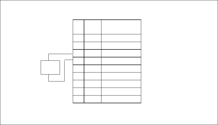
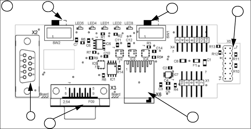
Fig. 1 - 51 1 Wire RS232 interface (03041578-01)
(1) CAN Bus Interface to I/O module (2) RS 232 Interface
(3) CAN Bus interface to the machine (4) Switch to recognize the version of the I/O mo-
dule Version 02/03
(5) Switch MA / PC switch to MA (machine) (6) Connector CAT5 cable
LED 1 nozzle changer gantry 1/3 LED 2 Temperatur sensor
LED 3 nozzle changer gantry 4/2 LED 4 Green "OK"
LED 5 Green "Fail"
4
1
2
3
1
5
6
1 Caccia Student Guide CACCIA Manual
Issue 04/2007 EN
78
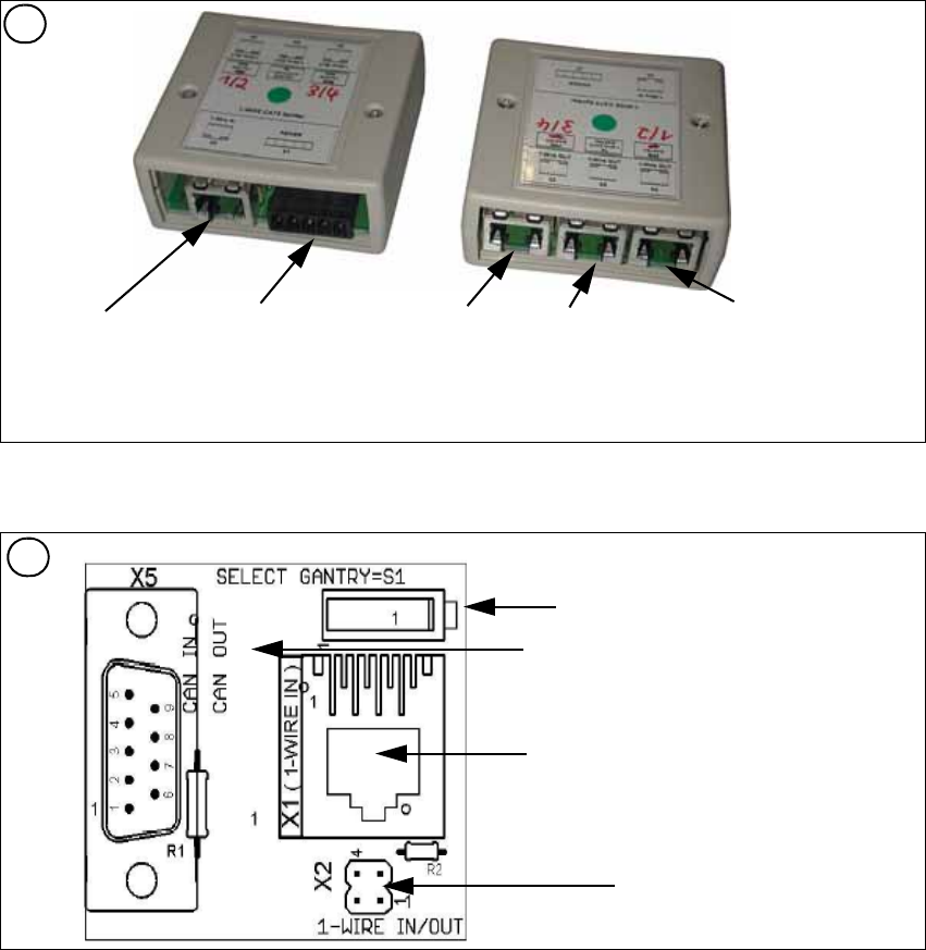
Fig. 1 - 52 1 Wire CAT 5 Splitter (03040219-01)
Fig. 1 - 53 1 Wire trailing interface board (03042214-01)
2
Input CAT 5 cable
from RS 232 Interface
Input 24 V for
NC
Output CAT 5
to the NC HUB
Gantry 3or 4
Output CAT 5 to
the 1 Wire gan-
try board
Output CAT 5
to the NC HUB
Gantry 1or 2
3
Switch: position below Gantry 1/2
position above Gantry 3/4
This board is located directly on the CAN
bus connector of the trailing interface.
Connector CAT5 cable from the 1 wire
distributor
Connection to the second Gantry in the
placement area