CAN Bus Workshop_Version 03__06-2008_EN.pdf - 第175页
CACCIA Manual 1 Caccia Student Guide Issue 04/2007 EN 83 Fig. 1 - 60 1 wire sub quer y structure Click on the "Query objects" button to display all P A1 s ubsystems. The function "Init 1wire" is not r…
1 Caccia Student Guide CACCIA Manual
Issue 04/2007 EN
82
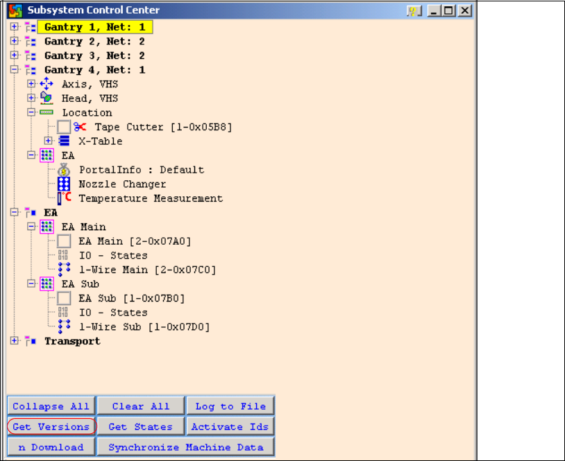
Fig. 1 - 59 Subsystem control
– Click on the "Get Versions" button.
The system will display all available subsystems with their firmware versions and CAN IDs.
– Doubleclick on the IO SUB (PA1) directory to open the 1 wire subdirectory. The following dialog
will appear:

CACCIA Manual 1 Caccia Student Guide
Issue 04/2007 EN
83
Fig. 1 - 60 1 wire sub query structure
Click on the "Query objects" button to display all PA1 subsystems.
The function "Init 1wire" is not required, as the one wire bus system is initialized when the machine
is switched on. (If initialization is necessary, you may need to click on the button 2 or 3 times.)
Allocation of subsystems to the hardware components
Example of PA1 on HF/HF3
Subsystem Hardware components Comments
Temperature, 1, coupler, 00 PCB:1 wire trailing interface Trailing interface gantry 1
Temperature, 4, coupler, 00
CB:1 wire trailing interface
Trailing interface gantry 4
PPW, 4, coupler, 00 1 wire hub for NC Hub for NC at location 4 for NC row 1/2
PPW, 1, coupler, 00 1 wire hub for NC Hub for NC at location 1 for NC row 1/2
Mainpath, 0, IO_2C, 01
Mainpath, 0, E2_512B, 01
1 wire RS232 bridge I/O module board (to be later integrated
into I/O module)
Temperature, 1, E2_512B, 81
Temperature, 1, E2_32B, 01
Temperature, 1, E2_512B, 61
Temperature, 1, temperature, 10
Temperature, 1, temperature, 11
Temperature, 1, IO_2C,01
Temperature sensors
gantry 1
The two temperature sensors form a unit
and can only be replaced as a set. The
part for the gantry recognition can not
change.

1 Caccia Student Guide CACCIA Manual
Issue 04/2007 EN
84
PPW --> Nozzle Changer (NC)
Temperature, 4, E2_512B, 81
Temperature, 4, E2_32B, 01
Temperature, 4, E2_512B, 61
Temperature, 4, temperature, 10
Temperature, 4, temperature, 11
Temperature, 4, IO_2C,01
Temperature sensors
gantry 4
The two temperature sensors form a unit
and can only be replaced as a set. The
part for the gantry recognition can not
change.
PPW, 4, E2 32B, 81
PPW, 4, AD, 03
PPW, 4, AD, 15
PPW, 4, AD, 16
1 wire hub for NC at location
4
Shows that the 1 wire hub is connected.
PPW, 4, E2_32, 01
PPW, 4, AD, 01
PPW, 4, IO_8C, 01
Control board in NC
gantry 4, in C&P20 NC only
Control board of NC row 1.
PPW, 4, E2_32, 02
PPW, 4, AD, 02
PPW, 4, IO_8C, 02
Control board in NC
gantry 4, in C&P20 NC only
Control board of NC row 2.
PPW, 1, E2_32B, 81
PPW, 1, AD, 03
PPW, 1, AD, 15
PPW, 1, AD, 16
1 wire hub for NC at location1 Shows that the 1 wire hub is connected.
PPW, 1, E2_32B, 01
PPW, 1, AD, 01
PPW, 1, IO_8C, 01
Control board in NC
gantry 1, in C&P20 NC only
Control board of NC row 1.
PPW, 1, E2_32B, 02
PPW, 1, AD, 02
PPW, 1, IO_8C, 02
Control board in NC
gantry 1, in C&P20 NC only
Control board of NC row 2.