CAN Bus Workshop_Version 03__06-2008_EN.pdf - 第233页
1 - 25 Siplace C AN T est B ox Edition 04 /2008 1 CAN T est Box 25 Comme nt s:
1 - 24
Siplace CAN Test Box
1 CAN Test Box Edition 04/2008
24
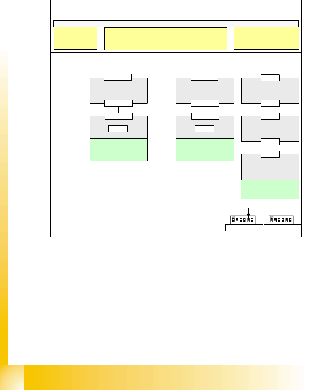
1.10.3 S27/S25 HM CAN Bus 1 MBit
The CAN bus structure is similar for S25 and F5. There is one gantry fewer for the F5 and different
conveyor control.
Fig. 1.10 - 5 CAN bus structure S27 HM with connector designations
CAN I/O module 2
(SLIO 2)
Transport control
board TSP201
Computer Unit
C
O
M
U
n
i
t
CAN Bus cable
1 MBit
X7sd
Distributor Board
Gantry 1
X6sd
X27aa
CAN I/O module 1
(SLIO 1)
X18ka
X18ka
X18kb
Backplane
CAN Bus cable
1 MBit
X3aa
Head board
Headprocessor
X23
Terminator
(120 Ohm)
DIP Switch
X3ac
Distributor Board
Gantry 2
X27ba
X3ba
Head board
Headprocessor
X23
Terminator
(120 Ohm)
DIP Switch
X3bc
Transport board
(CAN)
X3CAN
X18kb
X22kc
Terminator (DIP
Switch S1.5 =ON)
(120 OHM)
Axes boards
Single Conveyor Dual Conveyor
S1.5

1 - 25
Siplace CAN Test Box
Edition 04/2008 1 CAN Test Box
25
Comments:

1 - 26
Siplace CAN Test Box
1 CAN Test Box Edition 04/2008
26
1.10.4 Overview of CAN Bus Structures for HF and HF/3
HF
HF/3
Universal cable harnessOld cable harness
COM KSP354COM KSP 352
COM KSP 352 COM KSP354
SW 504 One
CAN bus per
machine
SW 505 One
CAN bus per
placement area
Version 01 Version 02
SW 504 One
CAN bus per
machine (was
not available)
SW 505 One
CAN bus per
placement area
COM KSP354COM KSP 352
SW 504 One
CAN bus per
machine
SW 505 One CAN
bus per placement
area (was not
available)
SW 505 One
CAN bus per
placement area
SW 504 One
CAN bus per
machine
Universal cable harnes
Version 02Version 01
Version 01 Version 02