CAN Bus Workshop_Version 03__06-2008_EN.pdf - 第217页
1 - 9 Siplace C AN T est B ox Edition 04 /2008 1 CAN T est Box 9 1.7 Ch eckin g the CAN Bus V olt age L evel The CAN level s for CAN_H and CAN_ L di fferentiate betwee n rece ssive an d dominant lev els. This two level s…

1 - 8
Siplace CAN Test Box
1 CAN Test Box Edition 04/2008
8
1.6 Checking the Power Fail, CAN Init, CAN Reset Sig-
nals
Note: Although the CAN Init and CAN Reset signals are not used in some cases (machine-spe-
cific), they still have a voltage level of 5V. The sporadic drop in voltage or a short circuit to other
signals could lead to logical faults in the CAN bus system (e.g. CAN timeout).
Should problems with the CAN bus occur, always check the signal voltage levels.
Step by step: 1
➠ Connect the CAN Test Box to the service plug (Note: Not all signals on the Service plug) of the
COM assembly.
➠ Switch the machine on.
➠ At the middle pin of the BNC socket, measure the CAN reset and power fail against ground,
for 5V DC voltage.
➠ The voltage level from the CAN init signal can be checked directly at the connector plug.
Note: In some machines, the wires for CAN init,CAN reset and power fail may have been removed
from the CAN bus cable at the COM assembly. In this case, the easiest way to check voltages
levels is at the RS232 bridge, in the main and sub distributors.
1.6.1 Error Localization
Should CAN bus errors occur sporadically, it may be helpful to check the signals during the pro-
duction process.
Trigger the signals and use the CAN Test Box and an oscilloscope to monitor the 5V voltages.
This helps you to determine whether the signals are really stabile and ensures that no sporadic
drops in voltage occur.
You will need to find a temporary solution for checking the CAN init signal (e.g. solder a wire to the
RS 232 connector plug), as this is not available at the CAN Test Box.
1 - 9
Siplace CAN Test Box
Edition 04/2008 1 CAN Test Box
9
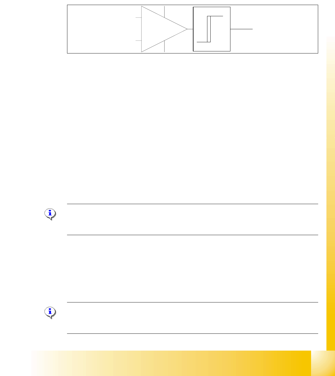
1.7 Checking the CAN Bus Voltage Level
The CAN levels for CAN_H and CAN_ L differentiate between recessive and dominant levels. This
two levels will convert into a TTL level, for the CAN Processor. The RxD Signal has the same
phase such as the CAN_L Signal.
Abb. 1.7 - 1 RxD signal
1.7.1 Checking the Recessive Level
The recessive level (when CAN bus is idle i.e. there is no data transmission) can be measured
statically, with a voltammeter. Make sure no telegrams are sent during the measurement proce-
dure. This means that measurement may only be performed when the machine is not in operation.
Step by step: 1
➠ Connect the CAN Test Box to the service plug (Note: Not all signals on the Service plug) of the
COM assembly.
➠ Switch the machine on and wait until it has booted.
➠ Measure the voltage level at the banana sockets between CAN H and GND or between CAN
L and GND, with the help of a measuring device.
➠ You should receive a voltage value of 2.5 V +/- 0.3 V for CAN_H and CAN_L.
Note: If you discover a short circuit or incorrect voltage level, disconnect the subsystems from
the CAN bus, one after the other. For suitable disconnection points, please refer to the circuit di-
agrams.
1.7.2 Checking the Dominant Level
The dominant CAN H and CAN L levels contain the information and need to reach a certain volt-
age level. These two CAN signals form a TTL CAN (RxD) signal, which can then be interpreted
by the CAN processor.
Note: You need an oscilloscope to measure the dominant level.To minimize the extent to which
the measurement system influences the CAN signals, keep the measurement line as short as pos-
sible.
CAN_L
CAN_H
RxD
TTL Pegel
(Level)
1 - 10
Siplace CAN Test Box
1 CAN Test Box Edition 04/2008
10
Step by step: 1
➠ Connect the CAN Test Box to the service plug (Note: Not all signals on the Service plug) of the
COM assembly.
➠ Connect the oscilloscope to the BNC sockets CAN_H and CAN_L.
➠ Set the measurement range for channels 1 and 2 to 1V and the sweep to 2μs
(see Fig. 1.7 - 3) and the trigger to channel 1.
➠ Switch the machine on and wait until it has booted.
➠ When the machine is in idle mode, position the signals on the oscilloscope into the center of
the screen.
➠ To simulate CAN bus communication, you can start a version query in Sitest or Caccia.
➠ Press the Stop button on the oscilloscope.
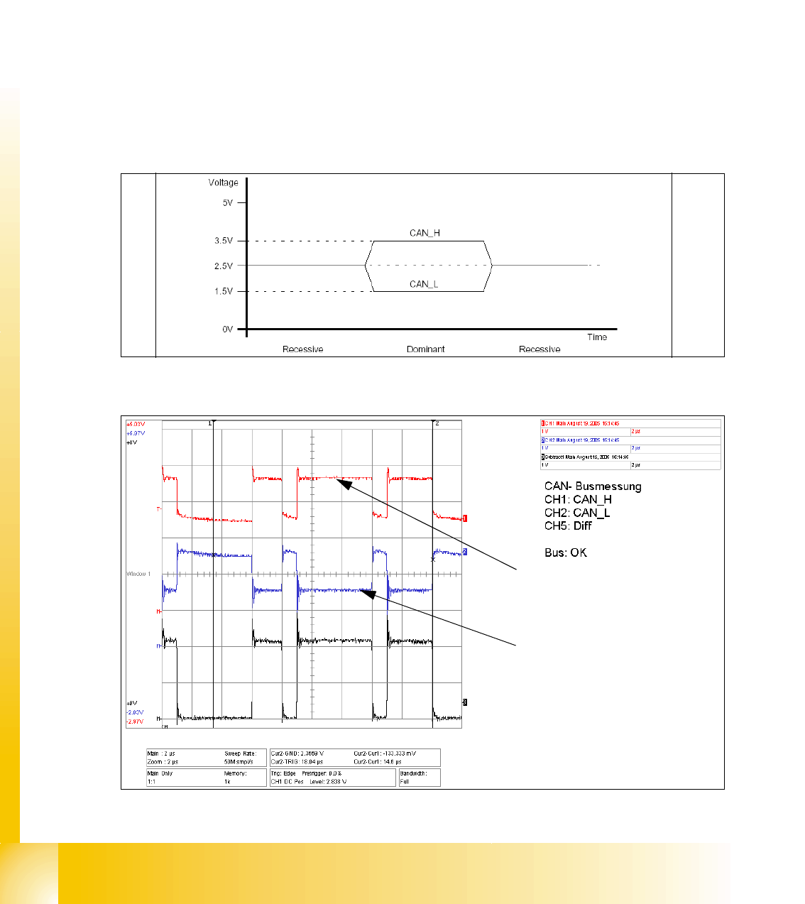
➠ You can now check the signal voltage levels. You should receive a value of 3.5V ( 2.75 - 4.5V)
for CAN_H and of 1.5V (2.0 - 1.0V) for CAN_L .
Fig. 1.7 - 2 Theoretical representation of recessive and dominant CAN_H and CAN_L signals
Fig. 1.7 - 3 Recessive and dominant CAN_H and CAN_L signal
Dominant CAN_H signal
Dominant CAN_L signal