CAN Bus Workshop_Version 03__06-2008_EN.pdf - 第58页
1 - 32 S tudent Gu ide CAN BUS Wor kshop 2 Commun icatio n and C ontrol Editio n 06/200 8 32 2.2.12 Communication X -Feeder The Comm unica tion b etween the Feed er Contr ol uni t (FCU) a nd eac h X- Fe eder is car ried …
1 - 31
Student Guide CAN BUS Workshop
Edition 06/2008 2 Communication and Control
31
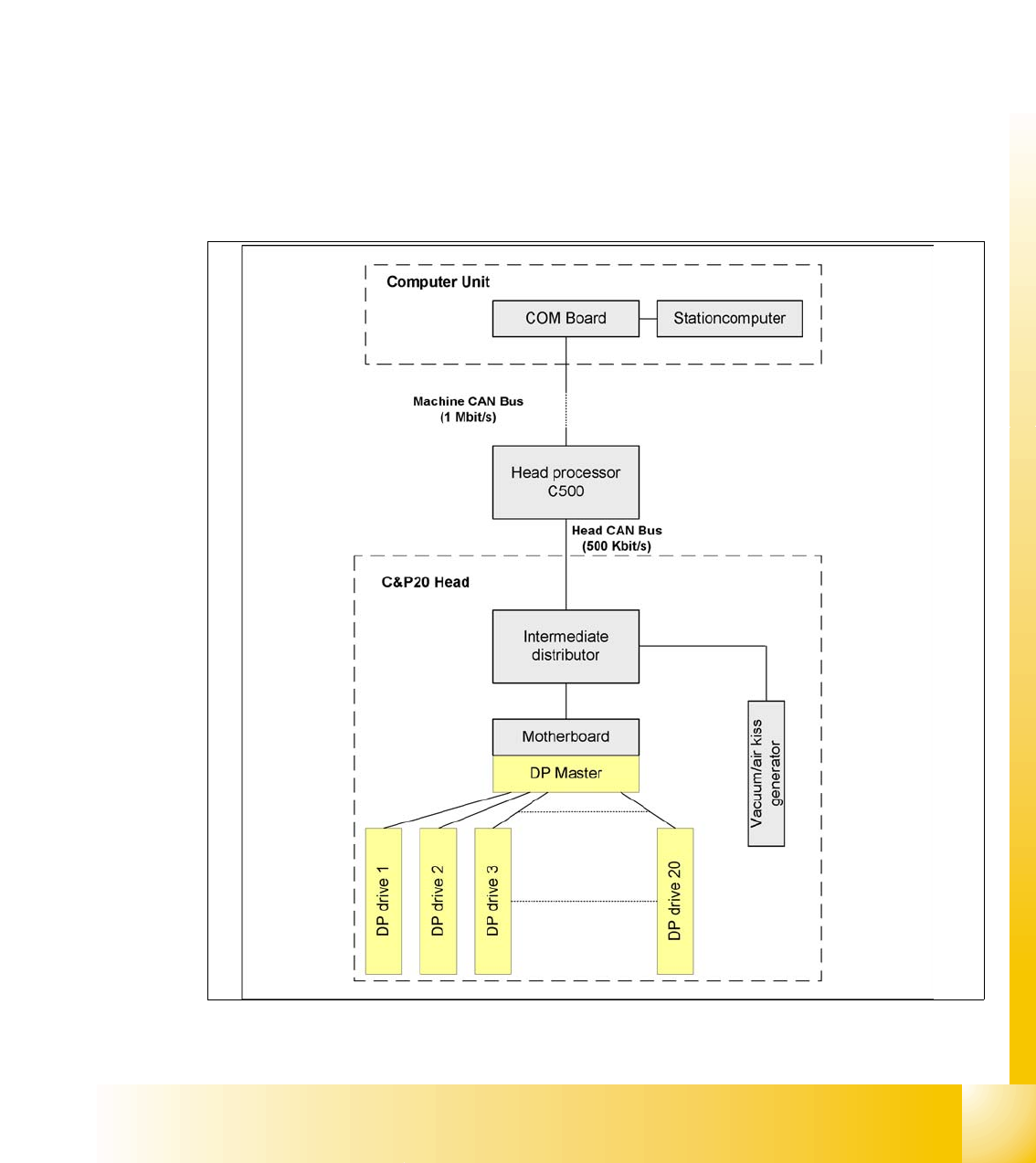
2.2.11 Communikation C&P 20 Head
The TQM –moduel on the head interface C500 is communicate via the CAN Bus (1M/Baud) to the
Machine controller.
The communication from the head interface to the C&P20 head is carried out with an additional
CAN Bus. Which send the data with 500KBaud.
The 20 DP - axes are controled via the „DP- Master" on the motherboard. So the machine CAN
Bus send 4 commands:
– Start the DP axis after Pick up/Placement (Pick up angle/Placement angle)
– Start the DP axis after Vision (Correction angle)
– Wait DP axis before Vision (Position commando not allowed)
– Wait DP axis before Pick up/Placement (Position commando not allowed)
Fig. 2.2 - 24 CAN-Bus controlled head function on the C&P 20 head
1 - 32
Student Guide CAN BUS Workshop
2 Communication and Control Edition 06/2008
32
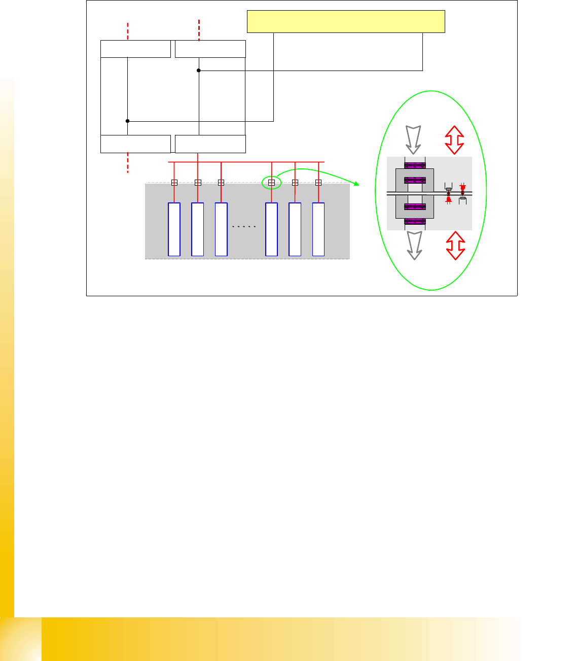
2.2.12 Communication X-Feeder
The Communication between the Feeder Control unit (FCU) and each X- Feeder is carried out via
a CAN bus. This CAN bus is only responsible for the communication between FCU and X-Feeder
and machines CAN bus controlled the "Feeder Can Bus". The data and power supply from the
FCU to each feeder is contactless.
Fig. 2.2 - 25 Communication X-Feeder
2.2.12.1 Tape Cutter and Nozzle Changer - Communication
Description of CAN node NC tape cutter module 2
The introduction of the SIPLACE X4I and the further development of the SIPLACE X series also
brings with it the integration of the nozzle changer control and the monitoring sensors into the
machine CAN bus. This new board is named "CAN node NC tape cutter module" [03052927-xx]
and is used in place of the former tape cutter board. This board contains the control system for
the tape cutter unit, NC 1 & 2, nozzle station (blast air valve for C&P20 head) and sensors for the
component/nozzles reject bin. The firmware for the CAN nodes is loaded onto the tape cutter
board with the help of the station software or CACCIA. The "CAN node NC tape cutter" is
backwards compatible with the old tape cutter boards. This assembly can therefore be used in X,
HF and D series machines.
SIPLACE
X-Serie
Feeder
Feeder
Feeder
Feeder
Feeder
Feeder
Feeder-CAN Bus
BE-Wagen
(COT)
Power Data
Power Data
Machine CAN Bus
FCU Location 1
C
O
M
U
n
i
t
x
6
p
n
x
7
p
n
FCU Location 2
FCU Location 3FCU Location 4
1 - 33
Student Guide CAN BUS Workshop
Edition 06/2008 2 Communication and Control
33
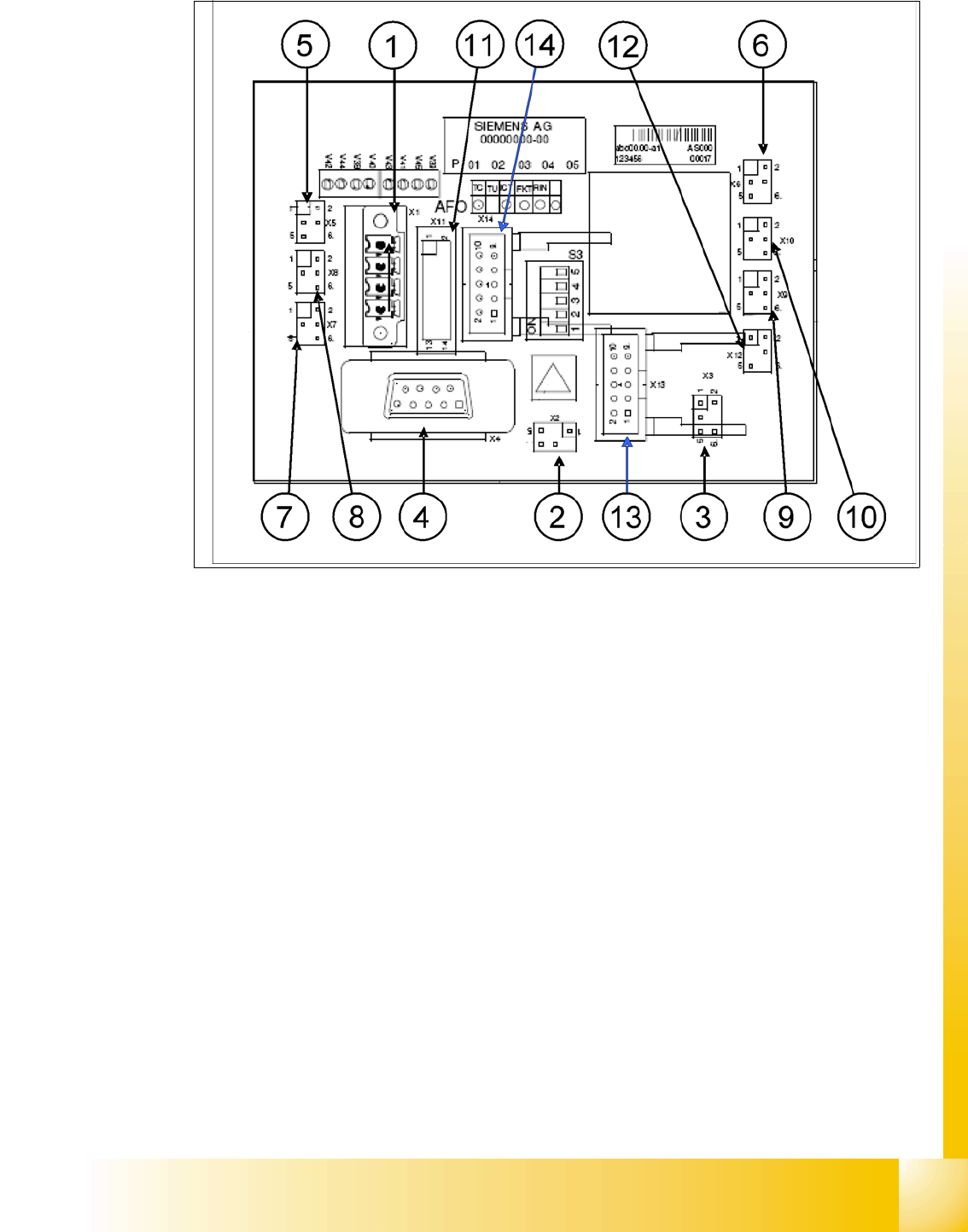
Fig. 2.2 - 26 Layout CAN node board
CAN node NC tape cutter module
1. X1 – Energy supply with automatic CAN ID
2. X2 – Energy supply, tape cutter +24 V/+5 V
3. X3 – Reject bin (nozzles, components)
4. X4 – CAN bus connection
5. X5 – Energy supply to valve (left)
6. X6 – Energy supply to valve (right)
7. X7 – Proximity switch for stroke cylinder in (left)
8. X8 – Proximity switch for stroke cylinder out (left)
9. X9 – Proximity switch for stroke cylinder in (right)
10. X10 – Proximity switch for stroke cylinder out (right)
11. X11– Test connector, tape cutter
12. X12 – Compressed air valve (additional pneumatic unit for rejecting components)
13. X13 – Nozzle changer, row 1
14. X14 – Nozzle changer, row 2