CAN Bus Workshop_Version 03__06-2008_EN.pdf - 第56页
1 - 30 S tudent Gu ide CAN BUS Wor kshop 2 Commun icatio n and C ontrol Editio n 06/200 8 30 2.2.10.1 Communication during a image acquisi tion The main comm unica tion betw een the vi sion sy stem and mac hinecont roll …
1 - 29
Student Guide CAN BUS Workshop
Edition 06/2008 2 Communication and Control
29
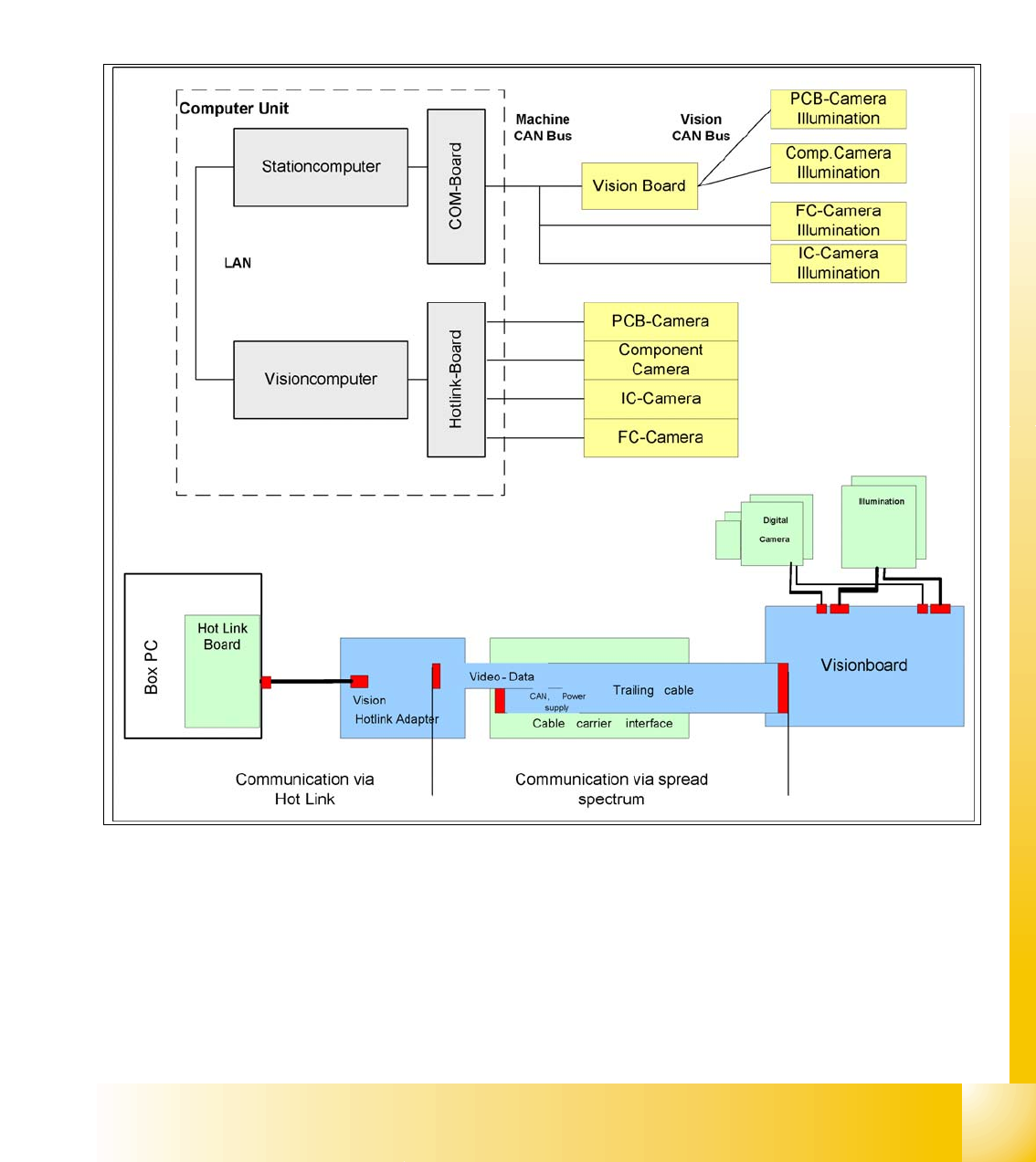
2.2.10 Communication Siplace Vision
The communication between the computers is via LAN cables. The station computer sends the
commands for image acquisition to the Vision computer and receives the measurement result.
The station computer also sends the illumination values for the respective component shapes.
The images recorded are transferred digitally via the Vision board to the hotlink adapter, using the
spread spectrum and are then sent via the hotlink connection to the Vision computer, for
evaluation. The result is sent to the station computer.
Fig. 2.2 - 21 Overview Siplace Vision
1 - 30
Student Guide CAN BUS Workshop
2 Communication and Control Edition 06/2008
30
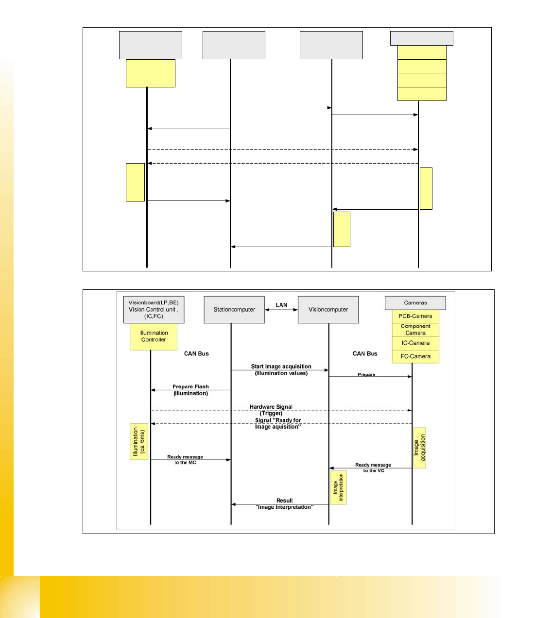
2.2.10.1 Communication during a image acquisition
The main communication between the vision system and machinecontroller is the transmission of
illumination values. These values, stored in the GF, are sent via CAN bus to the camera in ques-
tion. As soon as the camera should take the picture, the camera illumination is activated by a trig-
ger. From this moment on the row of LEDs which provide the different illumination levels light
dependant on the illumination value 0-255. This illumination value can have 0 = dark up to 255 =
bright. All illumination levels start lighting at the same moment. The value 0-255 determines the
length of the illumination time.The maximum length of illumination is limited to 6 ms.
Fig. 2.2 - 22 Time sequence from up to down for the Communication Image acquisition with SW60x
Fig. 2.2 - 23 Time sequence from up to down for the Communication Image acquisition with SW70x
Cameras
Illumination
Controller
Machine controller
(MC)
Stationcomputer with
Visionsoftware
Prepare
CAN Bus
Illumination
(ca. 6ms)
PCB-Camera
FC-Camera
IC-Camera
Component
Camera
Start Image acquisition
(Illumination values)
Prepare Flash
(illumination)
Hardware Signal
(Trigger)
Visionboard(LP,BE)
Vision Control unit ,
(IC,FC)
Ready message
to the MC
Signal "Ready for
Image aquisition"
CAN Bus
Image
interpretation
Image
acquisition
Ready message
to the VISION SW
Result
"Image interpretation"
1 - 31
Student Guide CAN BUS Workshop
Edition 06/2008 2 Communication and Control
31
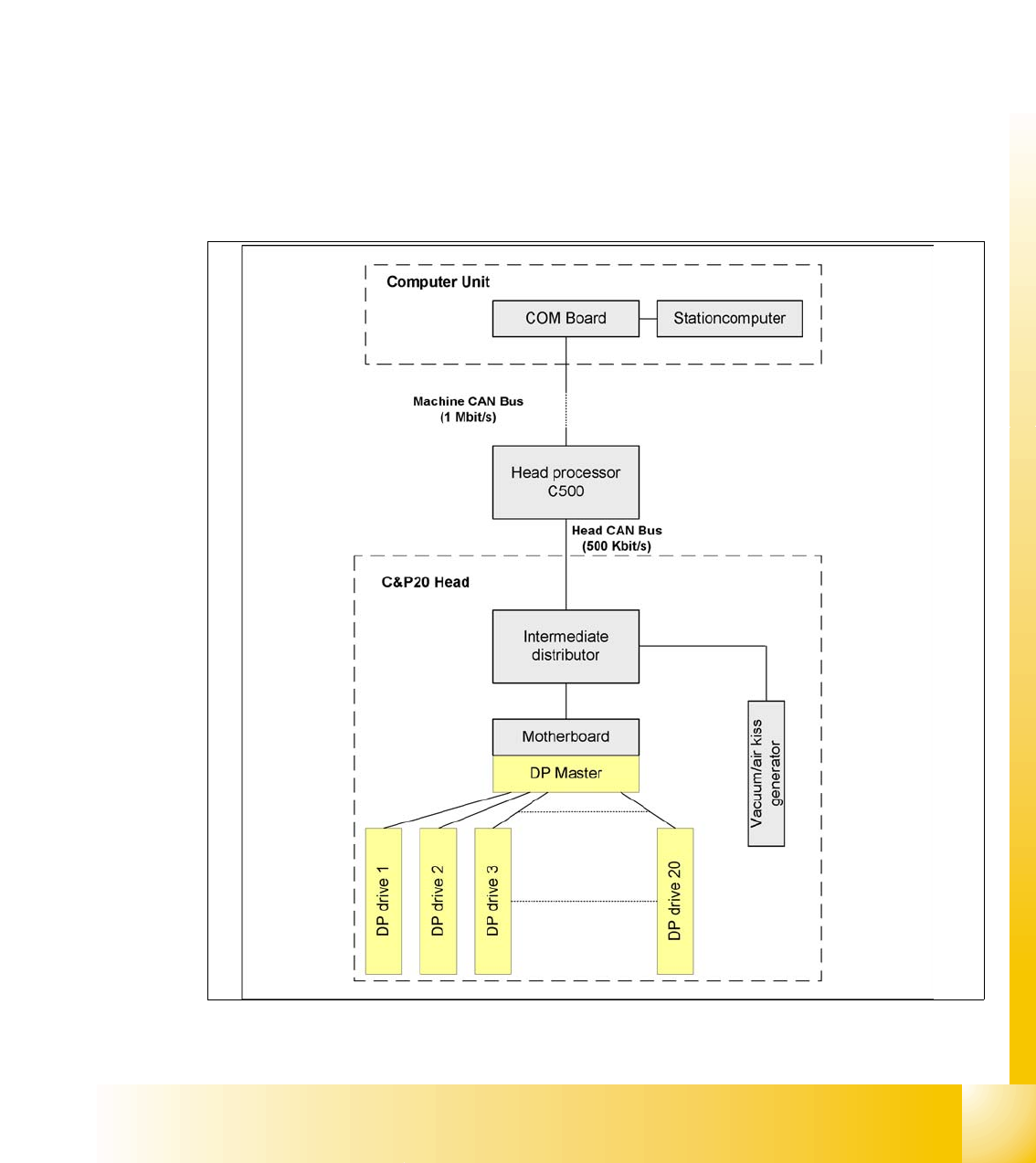
2.2.11 Communikation C&P 20 Head
The TQM –moduel on the head interface C500 is communicate via the CAN Bus (1M/Baud) to the
Machine controller.
The communication from the head interface to the C&P20 head is carried out with an additional
CAN Bus. Which send the data with 500KBaud.
The 20 DP - axes are controled via the „DP- Master" on the motherboard. So the machine CAN
Bus send 4 commands:
– Start the DP axis after Pick up/Placement (Pick up angle/Placement angle)
– Start the DP axis after Vision (Correction angle)
– Wait DP axis before Vision (Position commando not allowed)
– Wait DP axis before Pick up/Placement (Position commando not allowed)
Fig. 2.2 - 24 CAN-Bus controlled head function on the C&P 20 head