CAN Bus Workshop_Version 03__06-2008_EN.pdf - 第263页
1 - 55 Siplace C AN T est B ox Edition 04 /2008 1 CAN T est Box 55 1.10.9.1 CAN Bus Siplace X2 (V ariant 2) The CAN B us str ucture v ariant 0 1 for X2 machines was n ever del ieve red. The visi on con trol uni t is o nl…
1 - 54
Siplace CAN Test Box
1 CAN Test Box Edition 04/2008
54
1.10.9 CAN Bus Structure for Siplace X Machines
Attention: CAN bus structure!
There are two operation diagrams: 00194418-02.pdf and 00194418-01.pdf.
Always use operation diagram 00194418-02 for X2 machines or 00195280-01.The differences be-
tween this two circuit diagrams is only the introduction of the Box PC and A364.
For X3 and X4 machines, either one of the two operation diagrams may be used for the CAN bus
structure.
The CAN bus terminating resistors are located near gantries on which a C&P head is installed on
the head interface (C500). Gantries with a Twin Head will have a terminating resistor directly in-
stalled on the adapter board.
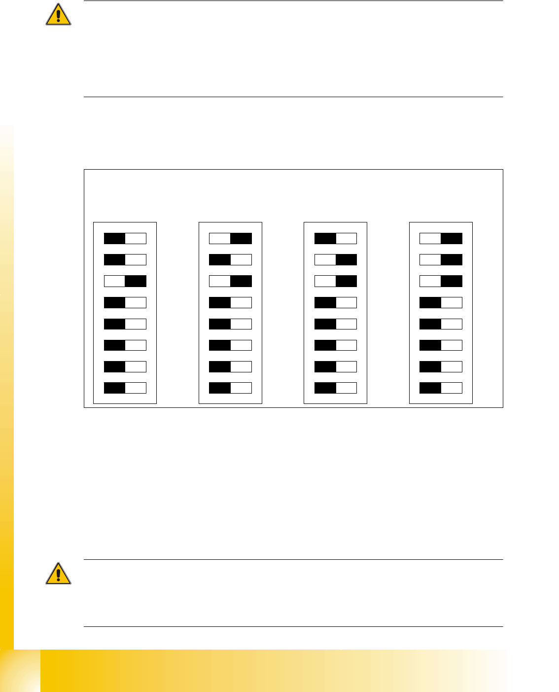
DIP switches configuration on the head interface (C500) with C&P heads
Key for DIP switches
Attention:
When using Head Modularity make sure that the terminating CAN resistor is set correctly. That
means, at the C&P heads switch CAN-Terminator ON and at the TWIN heads switch it OFF.(DIP
switch 3).
(1) P0 - Gantry address switch 1 (2) P1 - Gantry address switch 2
(3) CAN R - CAN terminator
(At TWIN-option always OFF)
(4) Boot - CAN Processor 16 Bit not mounted
(5) Reset - CAN Processor 16 Bit not mounted (6) C0 - CAN Address switch
(7) C1 - CAN Address switch (8) WPE - Write protect enable at the moment
OFF
DIP Switch
ON
78123456
ON
78123456
ON
78123456
ON
78123456
Ganty 1 Gantry 2 Gantry 3 Gantry 4
1 - 55
Siplace CAN Test Box
Edition 04/2008 1 CAN Test Box
55
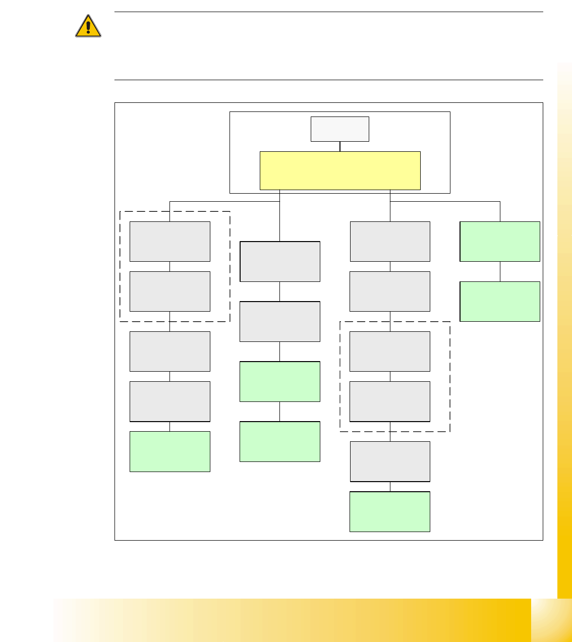
1.10.9.1 CAN Bus Siplace X2 (Variant 2)
The CAN Bus structure variant 01 for X2 machines was never delievered.
The vision control unit is only connected if you use an IC/FC camera version up to 03.
The IC/FC camera version upwards from 04 has the vision control unit in the camera and the cam-
era version 04 has its own CAN Bus connector.
Attention:
When you exchange a old stationary camera up to version 03 with a stationary camera
version 04, is it possible with a correct setting of the DIP switches to use the Vision Control unit in
the sectors. In this case the CAN Bus connector on the camera version 04 should not be used.
Fig. 1.10 - 31 CAN bus structure X2 in line with operation diagram 00194418-02
SMP BUS
Computer Unit
C
O
M
U
n
i
t
1
6
8
CAN Bus cable
PA1
X6pn
Trailing Interface
Gantry 1
Transport
Control unit
COT 1
Tape cutter
(optional stat.
Camera vers.04)
CAN I/O
SUB Modul
Sector 4
Vision Control unit
only for stat.
Cameras up to
Vers.03
COT 4 / MTC2
Tape cutter
SUB Distributor Sector 4
Terminator
120 Ohm
Head board(C500)
Gantry 1
Terminator
(120 OHM)
CAN Bus cable
PA 2
X7pn
Main Distributor Sector 2
COT 3
Tape cutter
(optional stat.
Camera vers.04)
Axis unit
PA 2
(only Axes for PA2)
CAN I/O
Main Modul
Sector 2
COT 2 / MTC2
Tape cutter
Trailing Interface
Gantry 3
Terminator
120 Ohm
Head board(C500)
Gantry 3
Terminator
(120 OHM)
Axis unit
PA 2
(only Axes for PA1)
MC
Vision Control unit
only for stat.
Cameras up to
Vers.03
1 - 56
Siplace CAN Test Box
1 CAN Test Box Edition 04/2008
56
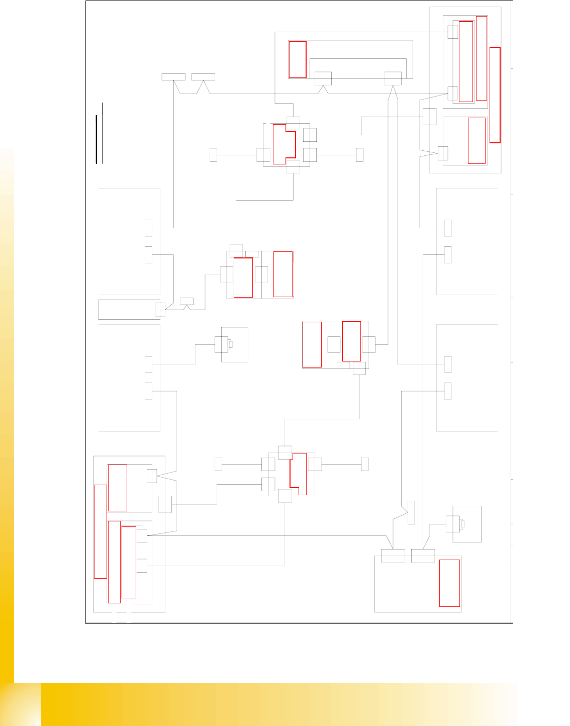
Fig. 1.10 - 32 CAN bus structure X2 operation diagram 00194418-02(1MBit)
Di 9
Vision-Steuerung
00363 961 (qd)
CAN
Hauptverteiler 0301 0004 (qa)
X2qd
X2qd
CAN
X2qf
Einzug 2 Einzug 1
X125X126
CAN-InCAN-Out
X115X116
CAN-InCAN-Out
CAN
LP-Steuerung
X22ao
X22ao
CAN I/O-Modul 00355 051 (qb)
Bu
StBuSt
Bu
Bu
0301 0050
0301 0051
X2rd
X145
CAN-In
Bu
Bu
Achseinschub 1/3
0301 6110
X30_2sq
CAN
Einzug 3
X136
CAN-Out
St
X2rd
CAN
CAN
Unterverteiler 0301 0005 (ra)
Vision-Steuerung
00363 961 (rd)
Einzug 4
0301 0054
Computereinschub
X135
CAN-In
Bu
Bu
X68
Umgebungsdrucksensor
Pneumatikeinheit
Bestückbereich 2
Bestückbereich 1
CAN-Bus Aderbelegung
AderNr. Belegung Sub-D- PIN
1
2
3
4
5
6
7
8
9
CAN
X30_2sq
X30_1sq
Bu
X30_1sq
Bu
X30_2tq
Bu
X30_1tq
X146
CAN-Out
St
Interface 1-Wire CAT5
0304 1578 (qf)
X2qf
X2rf
CAN I/O-Modul 00355 051 (rb)
Bu
0304 1578
Interface 1-Wire CAT5 (rf)
X2rf
BuX30_1sq
120 Ohm
Abschlusswiderstand
0302 7646
X1
Bu
X40da
St
0301 0052
0301 6643
X7pn X6pn
X7pn
Bu
CAN-Karte
X6pn
CAN-BUS 1CAN-BUS 2
Bu
0301 0059
X6qf
X6qf
0304 1626
Patchkabel 3m
X5rk
X5rk
Verteiler
0304 0219
0304 1626
Patchkabel 3m
X6rf
X6rf
0301 0053
X2rk
X1fq
X4rk
X1kq
X2rk
zum 1-Wire-Hub CAT5
zum 1-Wire-Hub CAT5
0304 1627
Patchkabel 3m
0304 1628
Patchkabel 3m
X15qa
X15qa
X15ra
X15ra
X1rk
X1rk
0300 9839
X3rk
X3rk
X4rk
Verteiler
0304 0219 (qk)
X5qk
X5qk
X3qk
X3qk
X1hq
X4qk
X2qk
X2qk
zum 1-Wire-Hub CAT5
X1gq
X4qk
zum 1-Wire-Hub CAT5
0304 1627
Patchkabel 3m
0304 1628
Patchkabel 3m
X1qk
X1qk
0300 9826
D
GND
CAN_INT
PowerFail
frei
RESET
"1-Wire"
CAN_H
CAN_L
GND
3
9
5
8
4
2
7
6
1
1-Wire CAT5
1-Wire CAT5
(rk)
Schalterpos.: oben
0304 2214 (he)
1-Wire CAT5 Portal
CAN In
Abschlusswiderstand
Schlepp Interface
Patchkabel 3m
0304 1629
X1he
X1he
X40ca
X5he
X2he
P3
X4he
CAN
X40ca
0301 0612
0302 7646
120 Ohm
X1
X40ba
Bu
0304 2214 (fe)
Schalterpos.: unten
X4fe
Schlepp Interface
X40aa
CAN
(ca)
0301 0612
P1
(aa)
X2fe
X5fe
1-Wire CAT5 Portal
X40aa
Bu
CAN In
Bu
X1fe
X1fe
Patchkabel 3m
0304 1629
Siehe Seite 3-20
Siehe Seite 5-35
Siehe Seite 5-28
Siehe Seite 3-13
e
Seite 5-72
Siehe Seite 5-35
Siehe Seite 3-9
Siehe Seite 4-16
Siehe Seite 5-70
Siehe Seite 5-55
S
eite 5-27
Siehe Seite 5-55
Siehe Seite 5-73
Siehe Seite 5-72
Siehe Seite 5-73
Siehe Seite 5-70