CAN Bus Workshop_Version 03__06-2008_EN.pdf - 第96页
1 Caccia Student Guide CACCIA Manual Issue 04/2007 EN 4 1.1.1 Configuration T oolbar Icons 1 Fig. 1 - 1 Caccia main view with configuration toolbar 1 1 Icon Designation Ta s k Calculator Op ens the Calculator dialog box.…

CACCIA Manual 1 Caccia Student Guide
Issue 04/2007 EN
3
1 Caccia Student Guide
1.1 CACCIA Functions
Caccia SIPLACE control concept in machines 1
Key Notes from the Programmer
Caccia is a R&D tool without restrictions. It supports a wide range of settings and functions. As
the Caccia user, you are personally responsible for the safe operation of software tools on the
placement machine. Do not change any parameters or functions if you are unsure of the results.1
1
Caccia has been developed in English. German texts are available in part but are not a fully sup-
ported feature. 1
Texts from databases or MA data files may be in English or German. Caccia has no influence on
these or on the language they are shown in. 1
1 Caccia Student Guide CACCIA Manual
Issue 04/2007 EN
4
1.1.1 Configuration Toolbar Icons
1
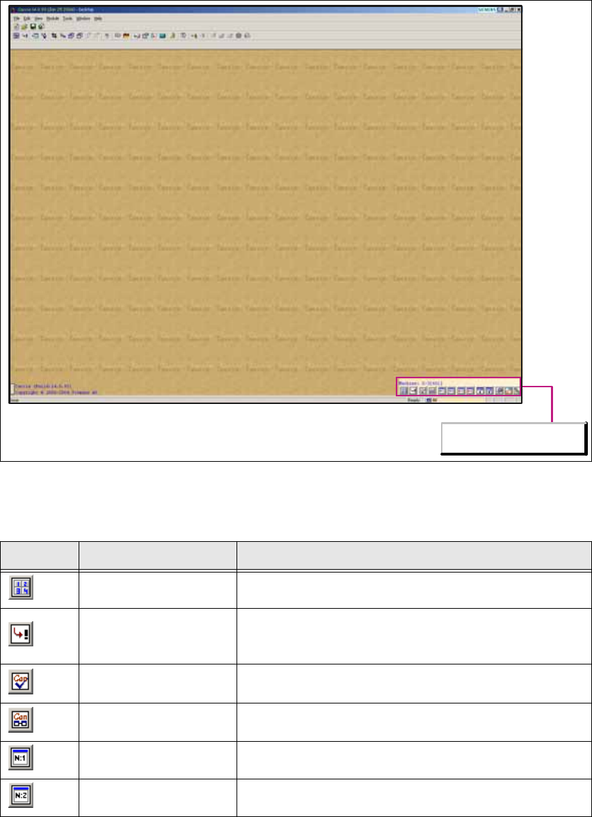
Fig. 1 - 1 Caccia main view with configuration toolbar
1
1
Icon Designation Task
Calculator Opens the Calculator dialog box.
Base Converter
Opens the Base Converter dialog box, in which values
can be converted into various number systems. Binary,
hex, oct and decimal figures can be converted here.
CAN Self test
Opens the CAN Self test dialog box, in which a Caccia
self-test can be initiated.
CAN Analyzer Opens the CAN Analyzer dialog box for Net 1 or Net 2.
Can Scope Net 1 Opens the Can Scope dialog box for Net 1.
Can Scope Net 2 Opens the Can Scope dialog box for Net 2.
Configurations Toolbar
CACCIA Manual 1 Caccia Student Guide
Issue 04/2007 EN
5
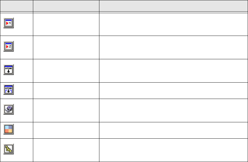
Tab. 1 - 1 Configuration Toolbar
1.1.2 CAN Selftest
Before you begin error localization, perform a software and wiring test: 1
→ Insert Kvaser or respective CAN-Test adapter into your computer and start the computer with
the respective profile.
→ Connect the two CAN transceivers to the Net1 and Net2 inputs of the CAN card.
→ Loop the SUB-D-connector of the CAN transceivers with the CAN ribbon cable and connect a
terminator.
→ You need to connect a minimum terminating resistance of 120 Ohm.
1
Make sure that the cable is connected properly: 1
– Net 1 at the left card output (front view).
– Net 2 at the right card output (front view).
Command Test Cen-
ter Net 1
Opens the Command Test Center dialog box for Net 1.
This function allows you to record the CAN Bus protocol
and address individual CAN nodes.
Command Test Cen-
ter Net 2
Opens the Command Test Center dialog box for Net 2.
This function allows you to record the CAN Bus protocol
and address individual CAN nodes.
Firmware Download
Opens the Download dialog box, in which a „non atten-
dant“ (unmonitored) firmware download can be per-
formed.
Serial Firmware
Download
Opens the A24 Download dialog box, in which a serial
firmware download can be performed.
Advanced Sub-
system Configura-
tion
Opens the Advanced Subsystem Configuration dia-
log box, in which the CAN card can be selected.
A KVASER card restart can also be performed here.
Machine Control
Opens the Machine Control dialog box, in which a
machine can be selected and subsystems configured.
Subsystem Control
Center
Opens the Subsystem Control Center dialog box, This
shows all subsystems in a tree structure, together with
the software/firmware versions.
Icon Designation Task