CAN Bus Workshop_Version 03__06-2008_EN.pdf - 第36页
1 - 10 S tudent Gu ide CAN BUS Wor kshop 2 Commun icatio n and C ontrol Editio n 06/200 8 10 Example : Arbitr ation with bit by bi t detec tion of 2 m ember s. Fig. 2.2 - 8 CAN- bus arbitration with 2 members If bus sub …
1 - 9
Student Guide CAN BUS Workshop
Edition 06/2008 2 Communication and Control
9
2.2.1.3 CAN Bus Arbitration
Arbitration (arbitration means decision)
In CAN networks, there is no addressing of subscribers or stations in the conventional sense, but
instead, prioritized messages are transmitted. Whenever the bus is free, any unit may start to
transmit a message. In general, a subscriber can only occupy the bus if this is free. The bus
subscriber can detect the bus occupation state by analyzing a certain time period within which the
bus must be inactive.
When multiple nodes begin to send a message at the same time, a selection phase (arbitration
phase) is used to decide which node may remain on the bus.
Bus access conflicts are resolved by including a message arbitration field (as a default the 11 bit
identifier is used).
The basis of bit-wise arbitration is the differentiation of 2 physical bus levels, a dominant one (low)
and a recessive bit (high).
A free bus is always on the recessive level. A DATA FRAME prevails over the REMOTE FRAME.
During arbitration every transmitter compares the level of the bit transmitted with the level that is
monitored on the bus. If these levels are equal the unit may continue to send.
When a recessive level is sent and a dominant level is monitored, the unit has lost arbitration and
must withdraw without sending one more bit. At the end of arbitration, the only subscriber left on
the bus is the one whose message has the lowest identifier value (logical zero is a dominant level).
The lower the identifier value is, the higher the priority of a message is.
When the bus is free any unit may start to transmit a message. The message sent by this
subscriber is not destroyed here i.e. it is a loss-free arbitration.
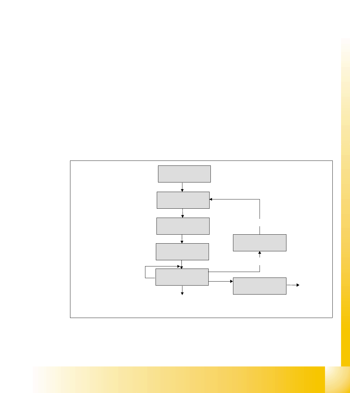
Fig. 2.2 - 7 flow chart bus arbitration
waiting if bus is free
bit SoF
bus in receiving state
1st bit of arbitration
transmitted
compare transmitted bit
level with bus level
bus in error state
arbitration lost?
recessive bit on dominant bus state
all arbitration bits are transmitted,
send control field and data field
next bits
START: Any member
will send a message
1 - 10
Student Guide CAN BUS Workshop
2 Communication and Control Edition 06/2008
10
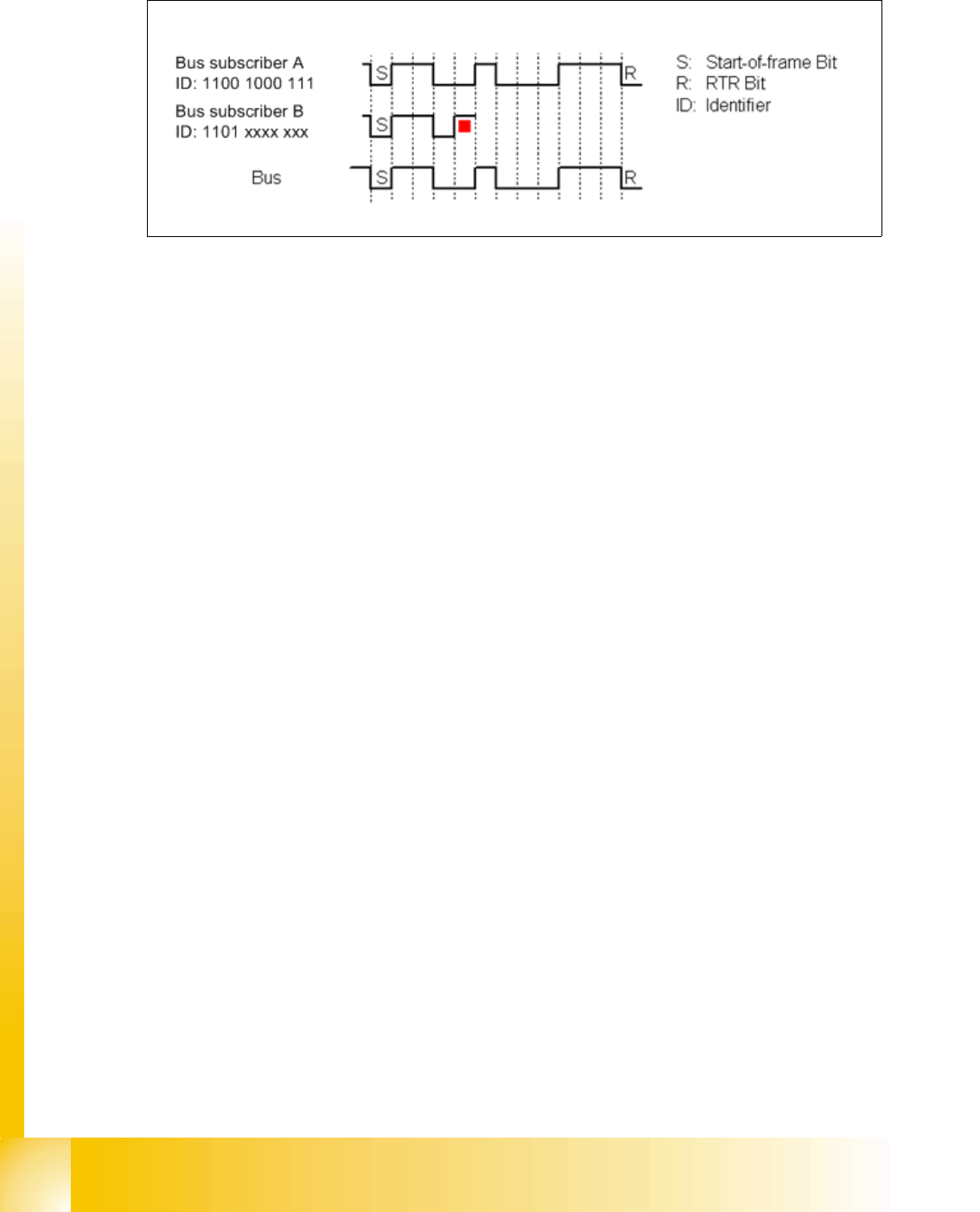
Example: Arbitration with bit by bit detection of 2 members.
Fig. 2.2 - 8 CAN- bus arbitration with 2 members
If bus subscriber A and B want to transmit, they begin to do so after the start-of-frame bit and
compare in each case the bits sent and received. Since"0" dominates on the bus, bus subscriber
B recognizes that the fourth bit differs from the bits sent and therefore withdraws from the bus until
the next start-of-frame. Bus subscriber A does not recognize a difference and therefore continues
to transmit. Messages with high priority therefore have an identifier which begins with several "0"s.
There are two bus states possible during arbitration: dominant and recessive.
2.2.1.4 Errors on the CAN Bus
Error frames
What are error frames?
Error frames are sent by the individual subsystems, if a command does not correspond with the
coding rules or if it has been corrupted i.e. when a CAN telegram has 6 or more consecutive bits
with the same level (high or low).
If a command is recognized by a subscriber, this subscriber immediately informs the other sub-
scribers and the telegram sender, by issuing an error frame.
Upon receipt of the error frame, all subscribers reject the telegram received and begin to send
their own error frames.
Once the bus is free again, the commend is resent.
If multiple error frames are issued, this indicates that a physical bus error has occurred. If too
many error frames are recognized during operation, a detailed analysis of the CAN signals is re-
quired.
1 - 11
Student Guide CAN BUS Workshop
Edition 06/2008 2 Communication and Control
11
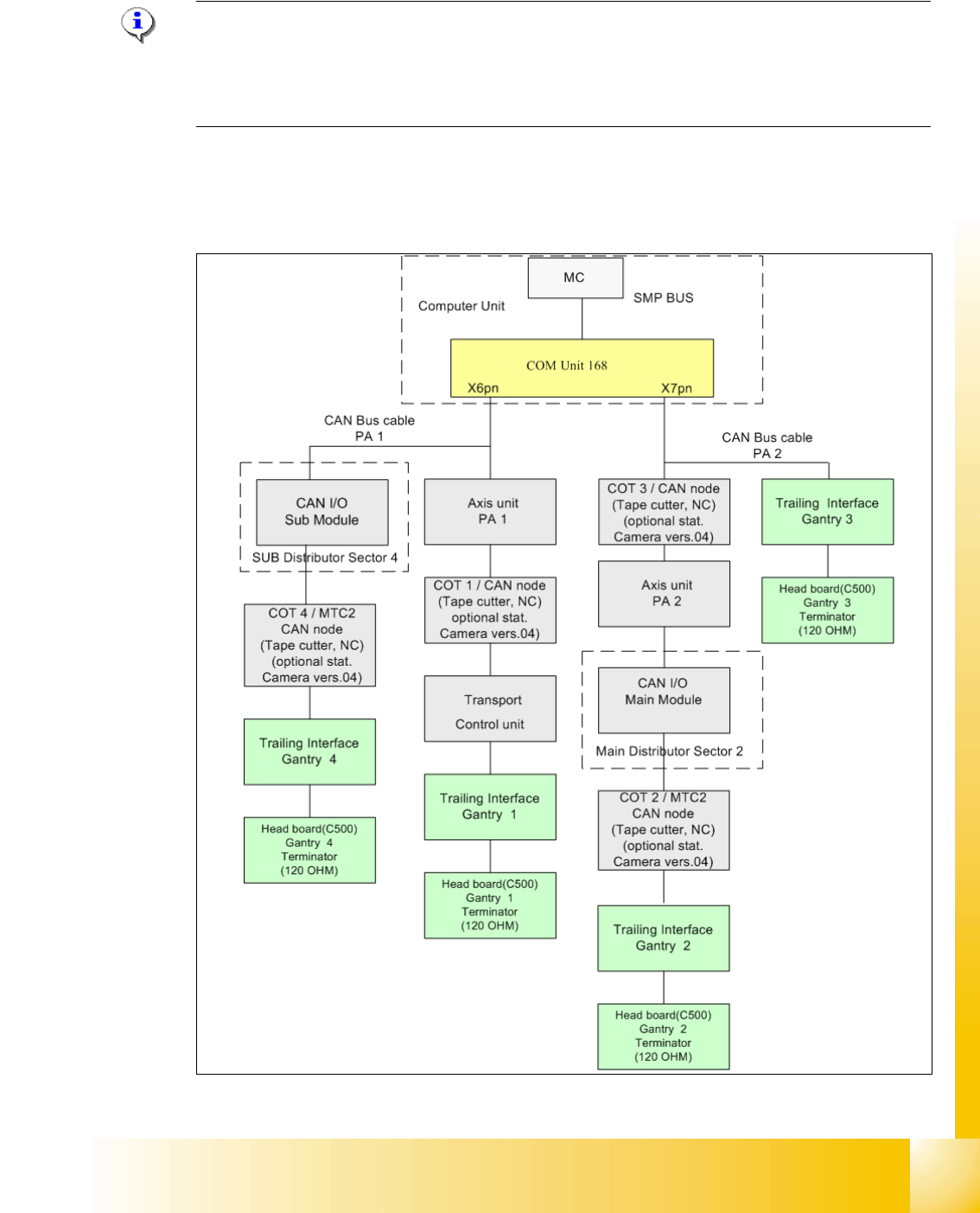
2.2.2 CAN Bus Concept Siplace X4
Note: In SIPLACE X machines, the machine controller is a box PC. This also contains the COM
unit. From approx. 2008 machines will not have separate illumination control as this is realized in
the stationary cameras from version 4 onwards. The NCs are addressed and the sensors moni-
tored by the CAN node module. The NC is therefore reintegrated into the CAN bus system.
The placement machine SIPLACE X uses a bus system with 1 Mbit/s transmission rate.The CAN:
Bus system begin at the Communication board and is split in 2 path. Every path is terminated by
a 120 ohm terminator on the head board at the individual placement head.
Fig. 2.2 - 9 CAN Bus overview Siplace X4