CAN Bus Workshop_Version 03__06-2008_EN.pdf - 第243页
1 - 35 Siplace C AN T est B ox Edition 04 /2008 1 CAN T est Box 35 Fig. 1.10 - 14 HF CAN bus struct ure (one CAN bus per P A, wit h old cable ha rness and KSP354) X 2 r d C A N C A N I / O - M o d u l 0 0 3 5 5 0 5 1 ( r…
1 - 34
Siplace CAN Test Box
1 CAN Test Box Edition 04/2008
34
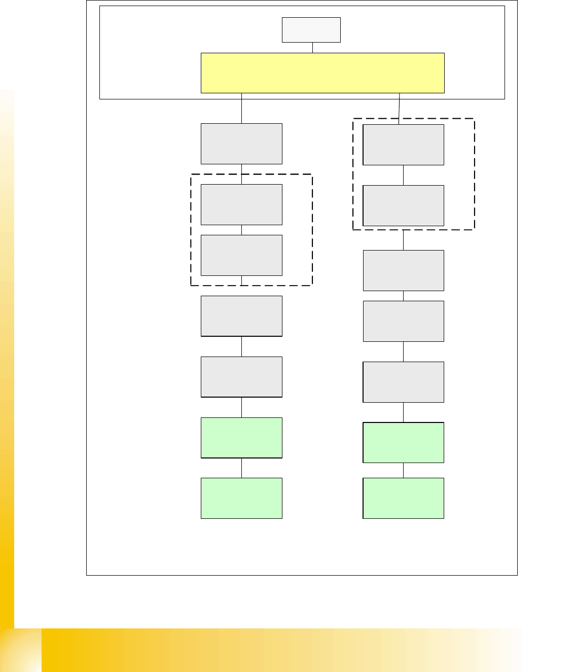
1.10.5.5 HF CAN Bus Structure With Old Cable Harness, KSP354 (SW 505 - Current)
CAN bus structure with SW 505.xx and COM assembly KSP354, with old cable harness (labeling
on cable = 0300xxxx-0x) and one CAN bus for each placement area.
Fig. 1.10 - 13 HF CAN bus structure (one CAN bus per PA, with old cable harness, KSP354)
SMP BUS
C
O
M
U
n
i
t
K
S
P
3
5
4
MC
CAN Bus cable 2
Computer Unit
For each Placementarea one CAN Bus!
* with SW 505 Gantry 2 is changed to Gantry 3
old cable loop!
new circuit diagram!
Trailing cable-
Interface
Gantry 1
Transport
COT 1
Tape cutter
Control unit
CAN Bus cable 1
CAN E/
A
Modu
l
Sektor
4
CAN E/
A
Modu
l
Sektor
4
CAN E/
A
Modu
l
Sektor
4
CAN I/O
SUB Module
Section 4
Vision
Control unit
SUB Distributor Section 4
Section 4
COT 4 / MTC
Tape cutter
Vision
Section 2
CAN I/O
Main Module
Section 2
Main Distributor Section 2
Control unit
COT 2 / MTC
Tape cutter
Axis unit
PA 2
COT 3
Tape cutter
Trailing cable-
Interface
Gantry 3*
x6pnx7pn
Head board(C500)
Gantry 1
Terminator
(120 OHM)
Head board(C500)
Gantry 3*
Terminator
(120 OHM)
x7pnx11pn
S1.2 = ON
Terminator
120 Ohm
S2.2 = ON
Terminator
120 Ohm
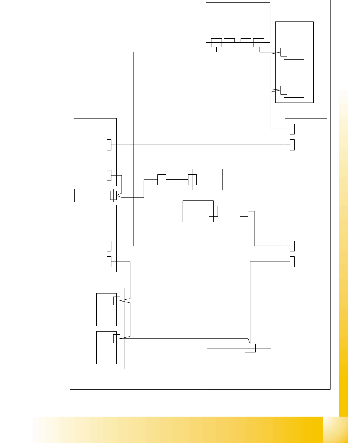
1 - 35
Siplace CAN Test Box
Edition 04/2008 1 CAN Test Box
35
Fig. 1.10 - 14 HF CAN bus structure (one CAN bus per PA, with old cable harness and KSP354)
X 2 r d
C A N
C A N I / O - M o d u l
0 0 3 5 5 0 5 1 ( r b )
X 1 r b
C A N
S u b D i s t r i b u t o r
0 3 0 0 1 5 3 2 ( r a )
X 2 r d X 1 r b
V i s i o n C o n t r o l - U n i t
0 0 3 6 3 9 6 1 ( q d )
C A N
M a i n D i s t r i b u t o r
0 3 0 0 1 5 3 1 ( q a )
X 2 q d
X 2 q d
C A N
X 1 q b
X 1 q b
A x i s U n i t 0 3 0 1 3 9 7 0
S c h l e p p I n t e r f a c e P 1
0 0 3 5 3 5 9 3
X 4 0 a a
C A N
( a a )
S c h l e p p I n t e r f a c e P 2
0 0 3 5 3 5 9 3
X 4 0 b a
C A N
( b a )
E i n z u g 2 E i n z u g 1
E i n z u g 3 E i n z u g 4
C O M - B g
X 9 s q
C A N
X 9 s q
X 4 0 b a
X 4 0 a a
X 7 p n
X 1 2 5X 1 2 6
C A N - I nC A N - O u t
X 1 1 5X 1 1 6
C A N - I nC A N - O u t
X 1 3 5 X 1 3 6 X 1 4 5X 1 4 6
C A N - I n C A N - O u t C A N - I nC A N - O u t
C A N
L P - S t e u e r u n g
X 2 2 a o
C A N - B u s 1 : C o m p u t e r U n i t - E i n z u g 2
0 3 0 0 3 5 6 0
C A N - B u s 1 :
E i n z u g 2 - M a i n D i s t . - A x i s U n i t - E i n z u g 3
0 3 0 0 3 5 6 1
C A N - B u s 1 : E i n z u g 3 - S c h l e p p I n t e r f a c e
0 3 0 0 3 5 6 2
C A N - B u s 2 : E i n z u g 4 - E i n z u g 1
0 3 0 0 3 5 6 4
0 3 0 0 3 5 6 5
C A N - B u s 2 :
E i n z u g 1 - L P - S t e u e r u n g - S c h l e p p I n t e r f a c e
C A N - B u s 2 : C o m p u t e r U n i t - S u b D i s t r . - E i n z u g 4
0 3 0 0 3 5 6 3
X 7 p nX 6 p n
C A N I / O - M o d u l
0 0 3 5 5 0 5 1 ( q b )
V i s i o n C o n t r o l - U n i t
0 0 3 6 3 9 6 1 ( r d )
X 2 2 a o
X 4 0 b a
X 4 0 b a
0 3 0 2 6 5 1 1
X 4 0 a a
0 3 0 2 6 5 1 1
X 4 0 a a
X 1 1 p n
f r e i f r e i
C A N - B u s 1 C A N - B u s 2
S 1 _ 2 u n d S 2 _ 2 a u f O N s e t z e n
( A b s c h l u s s w i d e r s t a n d 1 2 0 O h m )
C o m p u t e r U n i t 0 3 0 0 2 1 1 0
m i t K S P - C O M 3 5 4
X 1 2 p n
S t
B u
X 6 p n
1 - 36
Siplace CAN Test Box
1 CAN Test Box Edition 04/2008
36
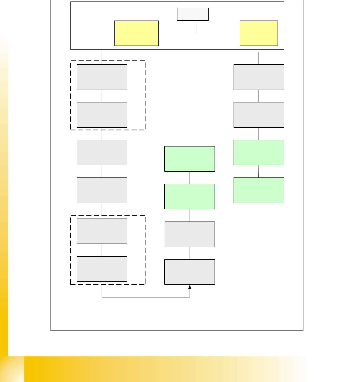
1.10.5.6 HF CAN Bus Structure With Universal Cable Harness, KSP352 (SW 504)
CAN bus structure with SW 504.xx and COM assembly KSP 352; with universal cable harness
(labeling on cable = 0301xxxx-0x); one CAN bus for both placement areas.
Fig. 1.10 - 15 CAN bus structure (one HF CAN bus with universal cable harness KSP352)
SMP BUS
MC
Axis unit
PA 2
Trailing cable-
Interface
Portal 1
CAN Bus cable
COT 3
Tape cutter
Computer Unit
One CAN Bus!
* SW Update 504 --> 505 Gantry 2 will be changed to gantry 3
new trailling cable !
old circuit diagram!
Trailing cable-
Interface
Gantry 2 *
Transport
COT 2 / MTC
Tape cutter
CAN E/
A
Modu
l
Sektor
4
CAN E/
A
Modu
l
Sektor
4
CAN E/
A
Modu
l
Sektor
4
CAN I/O
SUB Module
Section 4
Vision
Control unit
COT 1
Tape cutter
COT 4 / MTC
Tape cutter
SUB Distributor Section 4
Vision
Section 2
CAN I/O
Main Module
Section 2
Main Distributor Section 2
Section 4
Control unit
Control unit
x6pn
Head board(C500)
Gantry 1
Terminator
(120 OHM)
Head board(C500)
Gantry 2*
Terminator
(120 OHM)
C
O
M
U
n
i
t
K
S
P
3
5
2
(
r
i
g
h
t
)
C
O
M
U
n
i
t
K
S
P
3
5
2
(
l
e
f
t
)