CAN Bus Workshop_Version 03__06-2008_EN.pdf - 第68页
1 - 6 S tudent Gu ide CAN BUS Wor kshop 3 CAN BU S Editio n 06/200 8 6 7 Datum 06/2008 Ve rs ion 03 CAN Bu s Wo rkshop Mathias Mic h el SI PL ACE Ca m p us A utom ati o n and Dri ves 2. Aufb au CAN T ele gram m (all g em…
1 - 5
Student Guide CAN BUS Workshop
Edition 06/2008 3 CAN BUS
5
5Datum06/2008 Version 03 CAN Bus Workshop Mathias Michel
SIPLACE Campus
Automation and Drives
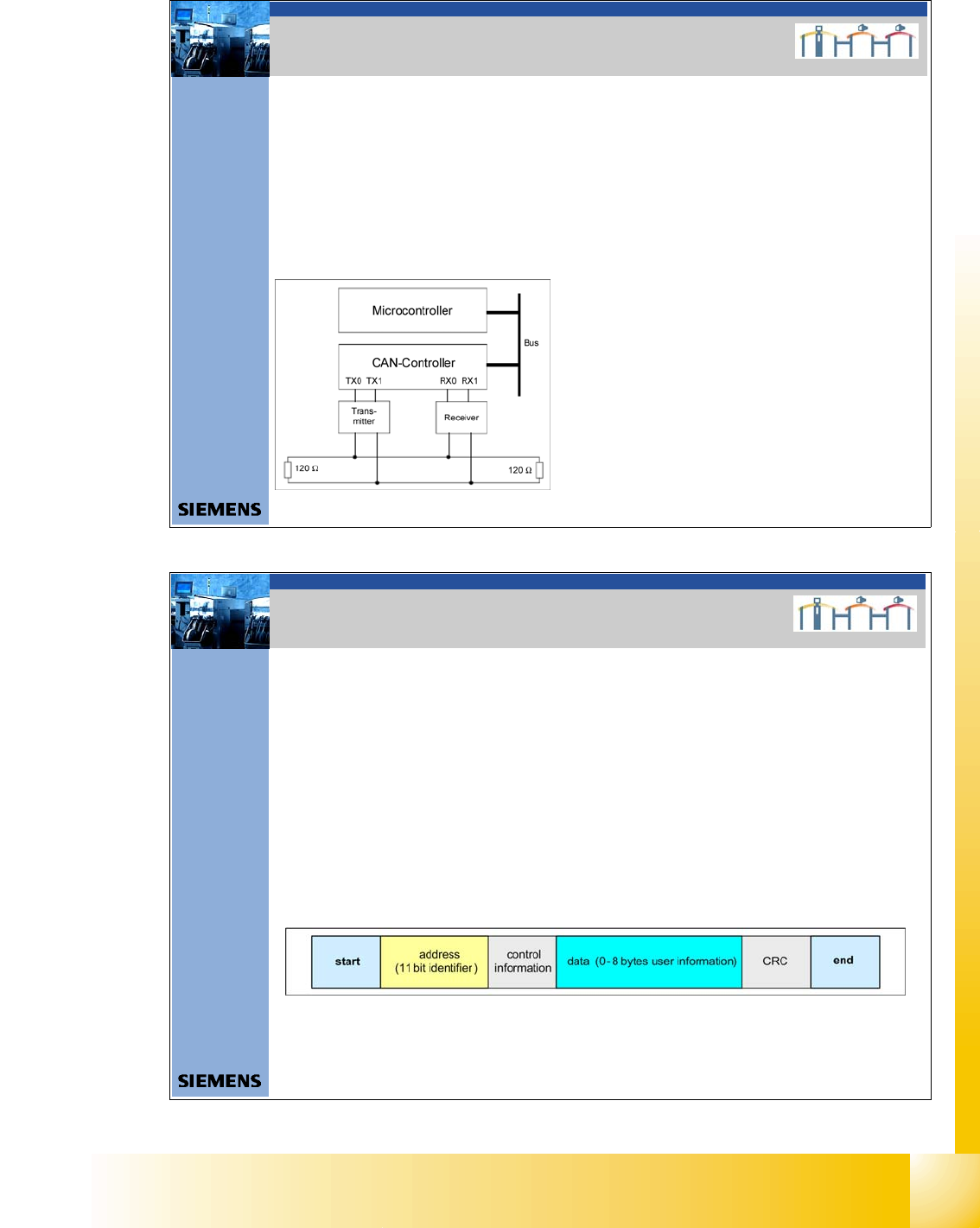
Each bus node has a CAN controller, which can transmit and receive data if
the bus is free.
This CAN controller communicates with a microcontroller. The microcontroller
steers and controls the relevant CAN bus nodes.
A CAN Bus node can only transmit if the bus is free i.e. if there is no
communication taking place with other nodes. Access to the CAN BUS is
fixed in the CAN protocol (identifier). This results in differing priorities among
the individual CAN bus nodes.
.
Function:
Microcontroller:- communicate to CAN Controller
- control the sensors, actuators and
control the function depend of the
Application.
CAN Controller: - add the data frame,
- built the connection to the
ComBoard
- Error handling
Transmitter/
Receiver: - adapt the level and amplify the
signal
2. CAN BUS Allgemeiner Aufbau
2. CAN BUS in general
6Datum06/2008 Version 03 CAN Bus Workshop Mathias Michel
SIPLACE Campus
Automation and Drives
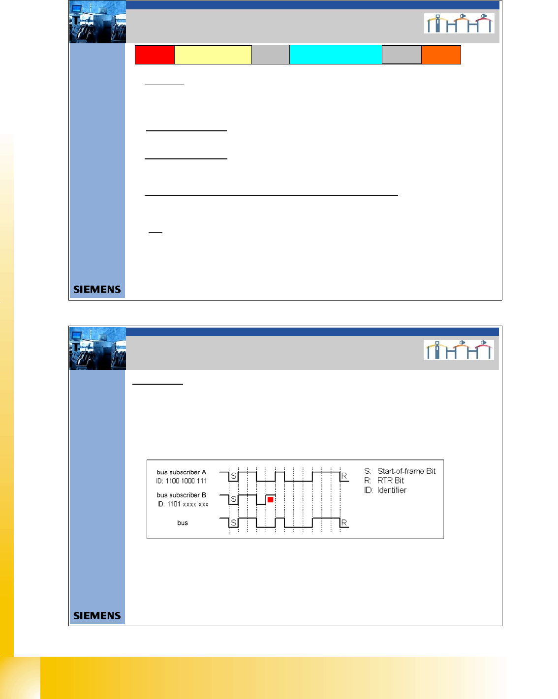
CAN-Telegram:
A CAN Telegram contains 0 up to 8 Datenbytes.
In the Siplace CAN Bus an 11 Bit Identifier (Address) identified the message.
(which kind of message, priority, source and / or target).
Therfore the Identifier control the access to the bus (Arbitrierung).
The identifier determines the priority of the messages, messages with high
priority will send directly and the others with delay.
CAN Bus systems can work with 11bit (Machine CAN BUS) or 29 bit (Sub
CAN Bus e.g. CAN node) Identifier.
2. CAN BUS Allgemeiner Aufbau
2. CAN BUS in general
1 - 6
Student Guide CAN BUS Workshop
3 CAN BUS Edition 06/2008
6
7Datum06/2008 Version 03 CAN Bus Workshop Mathias Michel
SIPLACE Campus
Automation and Drives
2. Aufbau CAN Telegramm (allgemein)
2. Construction CAN telegram
Start
Control
information
Data (0-8 Bytes user
information)
CRC
End
Start:Start: determines the telegram start. After this Bit is set, no other user of the Can Bus is able to
send.
Even 2 or more user set this bit at the same time, the arbitration decides the highest priority. The
address with the highest priority is allowed to send the telegram.
Address: Identifier field:
The value of this number is also the priority for bus access. The lowest number has the higher priority
Control information/DLC
Contains reserved bits and 4 bit DLC. The DLC (data length code) shows, how many Bytes are
transferred with the data field
CRC Sequence + CRC Delimiter = CRC Field (Cyclic Redundancy Check)
Each message is combined with a CRC word. Therefore it recognizes messages which are at least not
in an origin state while disturbances
End
The length of the end recognition is 7 Bit
Address
(11 Bit Identifier)
8Dat um06/2008 Version 03 CAN Bus Workshop Mathias Michel
SIPLACE Campus
Automation and Drives
Multi master:
When the bus is free any unit may start to transmit a message. The unit with the
message of the highest priority is transmitted at first.
Arbitration:
Whenever the bus is free, any unit may start to transmit a message. If 2 or more units start
transmitting messages at the same time, the bus access conflict is resolved by bitwise
arbitration using IDENTIFIER.
If the user A and B want to transmit a message, they begin to do after the start-of-frame bit
and compare in each case the bits sent and received. Since"0" dominates on the bus, user
B recognizes that the fourth bit is different from the bits sent and leave his message. User
B is waiting that the bus will free until the next Start-of-frame. User A recognize no different
and send continuous the message. Messages with high Priority have an Identifier, with a lot
of "0" bits.
There are two bus states possible during arbitration: dominant and recessive.
2. CAN BUS Arbitration
2. CAN Bus Arbitration

1 - 7
Student Guide CAN BUS Workshop
Edition 06/2008 3 CAN BUS
7
9Datum06/2008 Version 03 CAN Bus Workshop Mathias Michel
SIPLACE Campus
Automation and Drives
2. Aufbau CAN ID`s
2. Construction of the CAN ID`s
10 3456789 012
Channel
00 CMD = Comman d
01 ACK =Acknowledg e
10 DBG = Debugg
11 PUB = Public
Direction
0 - The Object send your own
Objekt Number.
1 - Message send the Objekt
Number which subsystem
have to received this
massege
Gantry
00 Gantry 1
01 Gantry 2
10 Gantry 3
11 Gantry 4
Object ID
- Head - Vision Objects
- Axis objects
- Component handling
- Tr ansport
- Safety
0 0000011 000
Example Head processor CAN ID 300 (hex)
Gantry 1
0 1000011 000
Example Head processor CAN ID 308 (hex)
Gantry 2
0 0100011 000
Example Head processor CAN ID 310 (hex)
Gantry 3
0 1100011 000
Example Head processor CAN ID 318 (hex)
Gantry 4
11 Bit Identifier
10Datum06/2008 Version 03 CAN Bus Workshop Mathias Michel
SIPLACE Campus
Automation and Drives
2. Aufbau CAN ID`s
2. Calculate CAN ID
0 1100011 000
Determine CAN ID
10 3456789 012
11 bit Identifier
Binär: 2 hoch X
1024 8163264128256512 124
0 816000256512 000
The result i s decimal 792 Æ calculate to HEX you get 31 8.
Variant 1:
Variant 2:
divide the Identifier into 4 bit block,
that way you get the HEX number easy
2 3012301 012
Binär: 2 hoch X
4 8124812 124
0 1100011 000
Excample Headprocessor
CAN ID 318 (hex)
Gantr y 4
0 8100012 000
Add the block you get directly the HEX number 318.
2 hoch X calculated
11 bit Identifier
Add block wise
31 8
Excample Headproc essor
CAN ID 318 (hex)
Gantry 4