CAN Bus Workshop_Version 03__06-2008_EN.pdf - 第113页
CACCIA Manual 1 Caccia Student Guide Issue 04/2007 EN 21 1 T ab. 1 - 3 Subsystem - action 1.3.2 CO Camera Illumination 1 → Click on the button to open the Subsystem Co ntrol Center d ialog box: 1 Fig. 1 - 1 1 CO camera i…
1 Caccia Student Guide CACCIA Manual
Issue 04/2007 EN
20
1.3 Function Check
The following requirements need to be met before some of the function checks can be per-
formed: 1
– SW release needs to be issued
– Security circuit must be closed
– Control needs to be switched on
– CAN IDs must be assigned to each subsystem to be tested
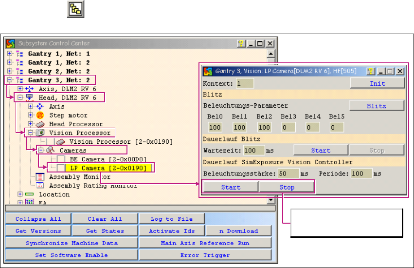
1.3.1 PCB Camera Illumination
→ Click on the button to open the Subsystem Control Center dialog box:
1
Fig. 1 - 10 PCB camera illumination function
Camera illumination
endurance test
CACCIA Manual 1 Caccia Student Guide
Issue 04/2007 EN
21
1
Tab. 1 - 3 Subsystem - action
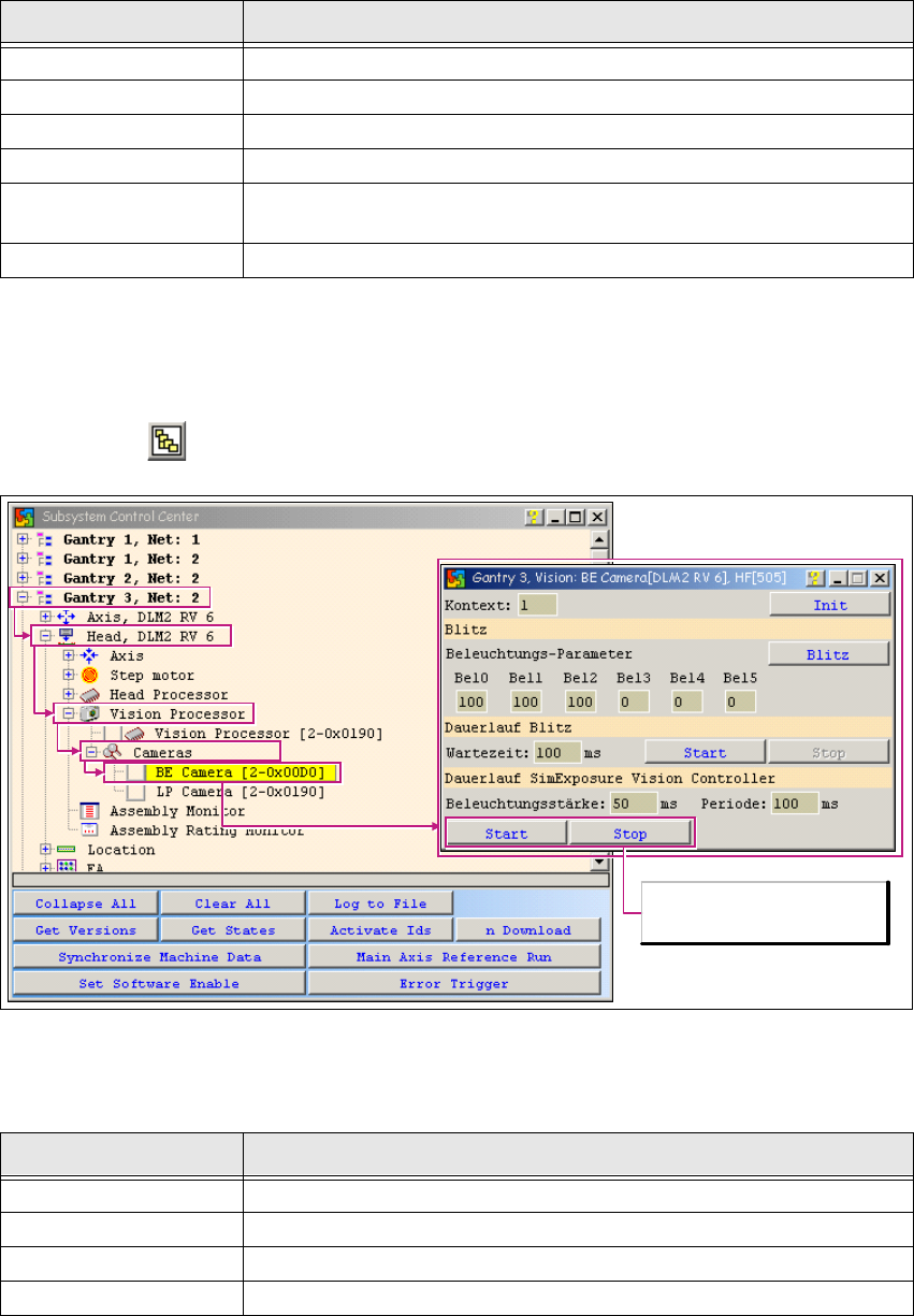
1.3.2 CO Camera Illumination
1
→ Click on the button to open the Subsystem Control Center dialog box:
1
Fig. 1 - 11 CO camera illumination function
1
1
Subsystem Action
Gantry Opens the relevant gantry. Gantry 3 is opened in the example.
Head VHS Opens the head function.
Vision Processor Opens the Vision processor.
Cameras Opens the Cameras submenu.
PCB Camera
Allows you to select the PCB camera with a doubleclick. The PCB
Camera dialog box will open.
Start, Stop Allows you to control the camera illumination endurance test.
Subsystem Action
Gantry Opens the relevant gantry. Gantry 3 is opened in the example.
Head VHS Opens the head function.
Vision Processor Opens the Vision processor.
Cameras Opens the Cameras submenu.
Camera illumination
endurance test
1 Caccia Student Guide CACCIA Manual
Issue 04/2007 EN
22
Tab. 1 - 4 Subsystem - action
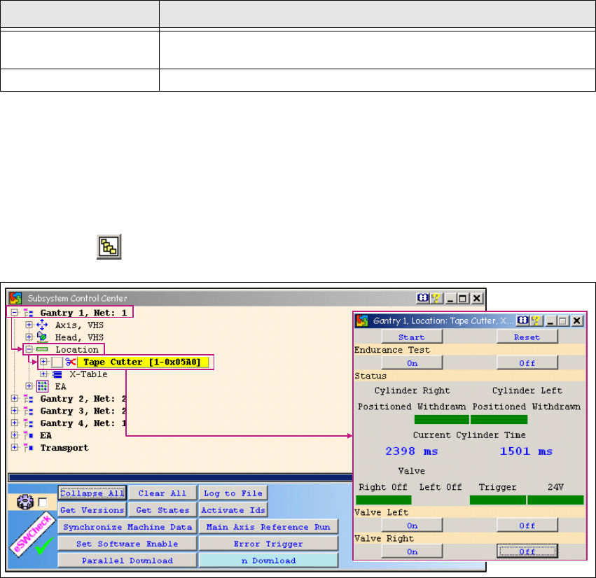
1.3.3 Tape Cutter
Due to the safety circuit, this function will only be available if the SW release has been issued and
the START button pressed. 1
l 1
→ Click on the button to open the Subsystem Control Center dialog box:
1
Fig. 1 - 12 Tape cutter function test
Procedure:
→ Click on the Start button in the Tape Cutter dialog box.
→ Switch the valves on and off, by clicking first the On button and then the Off button at Valve
Left and Valve Right. Current Cylinder Time shows the time the cylinders took to move in
and out.
→ The times shown should be within the following range:
– Move in: 1500ms +-500
– Move out: 2100ms +- 500
CO Camera
Allows you to select the PCB camera with a doubleclick. The CO
Camera dialog box will open.
Start, Stop Allows you to control the camera illumination endurance test.
Subsystem Action