CAN Bus Workshop_Version 03__06-2008_EN.pdf - 第166页
1 Caccia Student Guide CACCIA Manual Issue 04/2007 EN 74 1.1 1.1.2 One Wire Bus in the HF Machines The one wire bus in integrated into the machine CAN bus cable and therefore divided into place- ment areas 1 and 2 . The …

CACCIA Manual 1 Caccia Student Guide
Issue 04/2007 EN
73
1.11.1.1 Basic Structure
The one wire bus system consists in principle of a master with EEPROM (control unit), which con-
trols the various submodules such as A/D converters, EEPROM, temperature and I/O modules.
Each communication branch is equipped with an upstream coupler, which opens the branch for
data transfer.
Fig. 1 - 47 One wire bus principle
Slave
Master
Coupler
E²
A/D A/DA/D I/O
Coupler
E²
°C I/O°C
E²
Slave
1 Caccia Student Guide CACCIA Manual
Issue 04/2007 EN
74
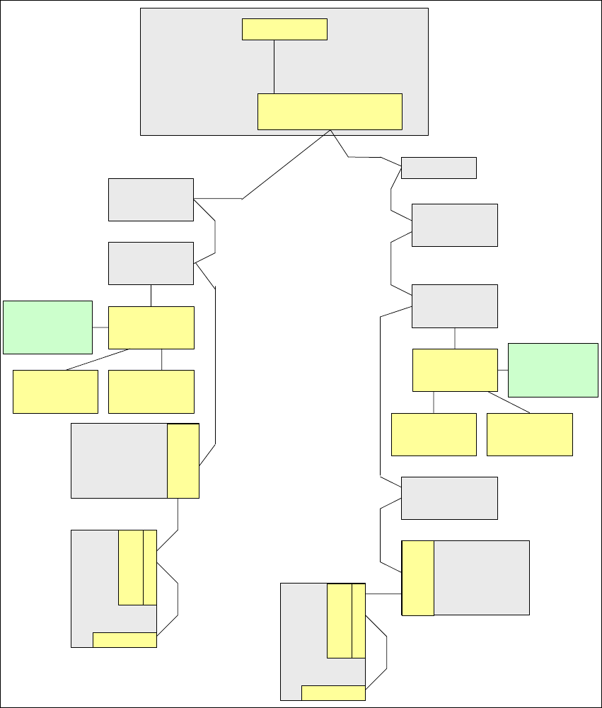
1.11.1.2 One Wire Bus in the HF Machines
The one wire bus in integrated into the machine CAN bus cable and therefore divided into place-
ment areas 1 and 2. The structure or arrangement of the CAN stations is identical with that of the
machine CAN bus. Pin 1 (wire 1) of the machine CAN bus is used for the one wire system.
Fig. 1 - 48 Overview of one wire subsystems e.g. BB1 on the HF machine
Vision
Control unit
Sector 4
Conveyor
Control
Axis unit
BB 1
Option: Check reject bin
or terminating plug
Attention: no CAN-
termination resistor
COM Board
I/O SUB Module
Sector 4
One Wire Bridge
(driver)
Nozzle Changer
Hub (Coupler)
Temp.sensor
CO-Table 4
Cutter
Head
plate
Control Board
NC (C&P20)
Row 1
Control Board
NC (C&P20)
Row 2
Trailing Unit Interface
Gantry 4
1 Wire Board
(Trailing Unit
Interface)
Temp.sensor
Nozzle Changer
Hub (Coupler)
CO-Table 1
Cutter
Control Board
NC (C&P20)
Row 1
Control Board
NC (C&P20)
Row 2
Trailing Unit Interface
Gantry 1
1 Wire Board
(Trailing Unit
Interface)
Temp.sensor
Head
plate
Temp.sensor
Gantry
recognition
Option: Check reject bin
or terminating plug
Attention: no CAN-
termination resistor
TQM Module
(Master)
RS232
Machine CAN Bus with
One Wire
Gantry
recognition
CACCIA Manual 1 Caccia Student Guide
Issue 04/2007 EN
75
Depending on the machine configuration (1 or 2 gantries) the one wire bus structure in PA2 is iden-
tical with that in PA1.
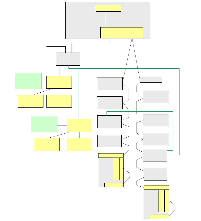
1.11.1.3 One Wire Bus in the Siplace X
With the Siplace X-machine the One Wire Bus is integreted in a separate CAT5 cabel, which start
from the Main- and Subdistributor up to the trailling interface. From the trailing interface up to the
head interface the one wire bus goes through the trailling cable. So that the cable structur are dif-
ferent but not the function of the one wire bus. 1
1
Fig. 1 - 49 Overview of one wire subsystems e.g. PA1 on the Siplace X
Vision control
unit
Sector 4
Transport
Control unit
Axis unit
PA 1
COM Board
I/O SUB Module
Sector 4
One Wire Bridge
(driver)
Nozzle changer
Hub (Coupler)
Gantry 4
CO-Table 4
Tape cutter
Conrol board
NC (C&P20)
row 1
Control board
NC (C&P20)
row 2
Trailing -Interface
Gantry 4
CO-Table 1
Tape cutter
Trailing-Interface
Gantry 1
Temp.sensor
Head
plate
Temp.sensor
Option: Check reject bin
or terminating plug
Attention: no CAN-
termination resistor
TQM Module
(Master)
RS232
Machine CAN Bus
1 Wire CAT5
Gantry 4
Headinterface
1 Wire CAT5
Gantry 4
Temp.sensor
Head
plate
Temp.sensor
Gantry
recognition
Headinterface
1 Wire CAT5
Distributor
24V for the nozzle changer
1 Wire CAT5 cable
1 Wire CAT5 cable
1 Wire CAT5 cable
1 Wire CAT5 cable
1 Wire CAT5 cable
Nozzle changer
Hub (Coupler)
Gantry 1
Control board
NC (C&P20)
row 2
Conrol board
NC (C&P20)
row 1
Option: Check reject bin
or terminating plug
Attention: no CAN-
termination resistor
Gantry
recognition