CAN Bus Workshop_Version 03__06-2008_EN.pdf - 第110页
1 Caccia Student Guide CACCIA Manual Issue 04/2007 EN 18 1 Fig. 1 - 9 Subsystem Control Center dialog box – If the tick is set , you will only see respond ing subsystems with - a minimum of - loaded BIOS versions. In thi…
CACCIA Manual 1 Caccia Student Guide
Issue 04/2007 EN
17
When you start the machine controller (MC), the individual CAN subsystems are automatically as-
signed machine type-specific CAN addresses or CAN IDs. These are required for requests, down-
loads or function calls. 1
If the MC is unable to start or if it is blocked by an empty diskette, Caccia can perform a machine
type-specific CAN ID assignment with the Activate Ids button. 1
– Once this has been completed, you can perform downloads.
– To execute other functions, you will need the correct CAN ID and CAN BUS command.
– A few functions also require the software release signal and pressing of the machine START
button.
1.2.3 Opening the Subsystem Control Center with (eSW) Firmware Check
Note
The requirements for using the eSWCheck Database option are explained in Section „Embedded
Software Check (eSW) Check DataBase“ auf Seite 12. 1
→ Click on the button to open the Subsystem Control Center dialog box:
The general operation of the Subsystem Control Center is described in Chapter 1.2.3 „Ope-
ning the Subsystem Control Center with (eSW) Firmware Check“ auf Seite 17. 1
The eSW Firmware Check functions are available when the eSWCheck icon is shown and the
tick has been set. 1
1 Caccia Student Guide CACCIA Manual
Issue 04/2007 EN
18
1
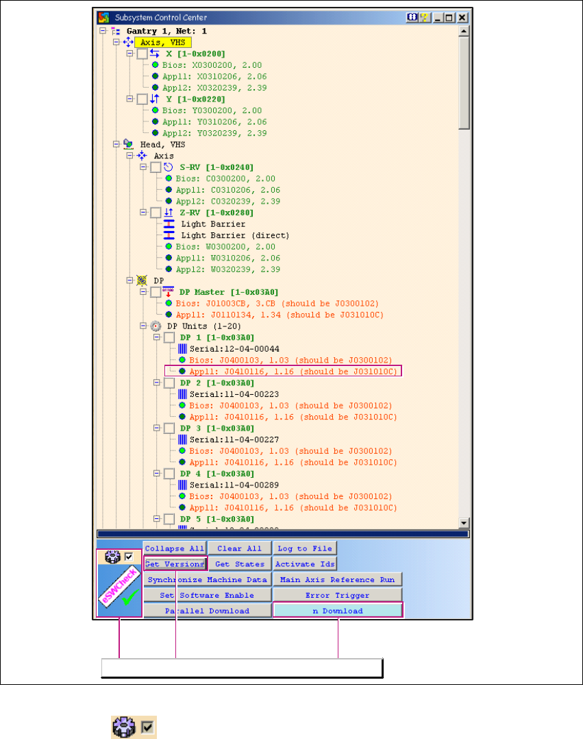
Fig. 1 - 9 Subsystem Control Center dialog box
– If the tick is set , you will only see responding subsystems with - a minimum of - loaded
BIOS versions. In this case, the eSW Check can be performed by clicking on the Get Versions
button. The different eSW versions will be shown behind the respective CAN subsystem. If
there is no difference between the software versions, the tree structure will remain closed and
the CAN subsystem will be marked green.
– The eSW Check is only performed for CAN subsystems which are connected to the CAN Bus.
The eSW Check functions will be available.
CACCIA Manual 1 Caccia Student Guide
Issue 04/2007 EN
19
– The (eSW) firmware version marked in the diagram shows the current SW J0410116 on the
subsystem axis controller and compares this to the version in the firmware folder XML file. In
this case, this is the file J031010C.
– The exact meaning of firmware file names is explained in Chapter 1.6.4 „Download - File Code“
auf Seite 48.
– If CAN test leads are incorrectly connected to the station, the version request and other actions
will fail.
1
How to correctly connect CAN test leads to the station:
→ Net 1 (left card output) is connected to the CAN1 connector (top) of the COM assembly in the
X-series machine computer unit.
→ Net 2 (right card output) is connected to the CAN2 connector (bottom) of the COM assembly
in the X-series machine computer unit.