CAN Bus Workshop_Version 03__06-2008_EN.pdf - 第32页
1 - 6 S tudent Gu ide CAN BUS Wor kshop 2 Commun icatio n and C ontrol Editio n 06/200 8 6 2.2 CAN Bus The develo pment of CAN b egan wh en more and mo re electr onic dev ices wer e implem ented into modern mo tor vehi c…

1 - 6
Student Guide CAN BUS Workshop
2 Communication and Control Edition 06/2008
6
2.2 CAN Bus
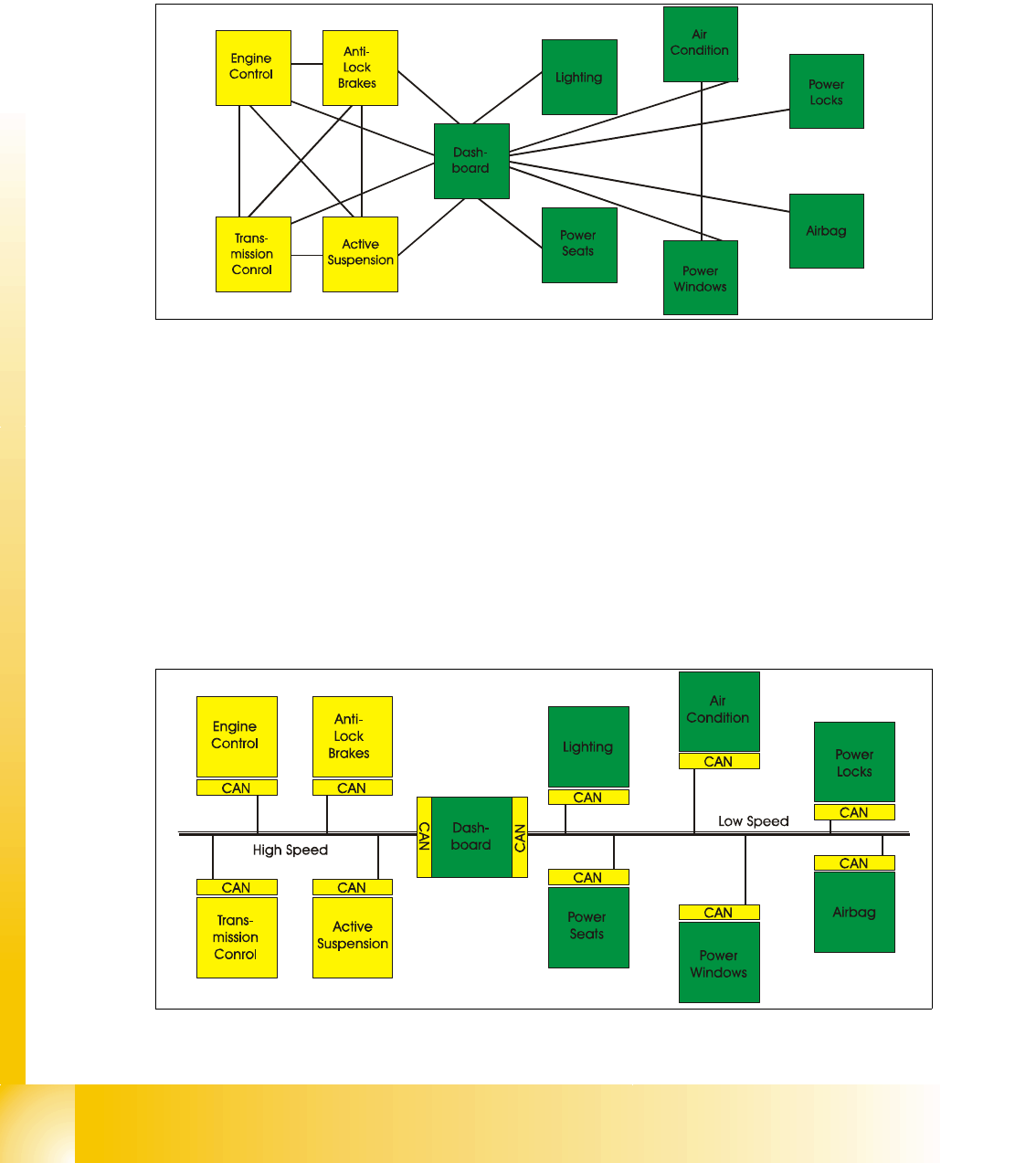
The development of CAN began when more and more electronic devices were implemented into
modern motor vehicles. Examples of such devices include engine management systems, active
suspension, ABS, gear control, lighting control, air conditioning, airbags and central locking. All
this means more safety and more comfort for the driver.
Fig. 2.2 - 1 communication via cable connection
To improve the behavior of the vehicle even further, it was necessary for the different control sys-
tems (and their sensors) to exchange information. This was usually done by discrete interconnec-
tion of the different systems (i.e. point to point wiring). The requirement for information exchange
has then grown to such an extent that a cable network with a length of up to several miles and
many connectors was required. This produced growing problems concerning material cost, pro-
duction time and reliability.
The solution to this problem was the connection of the control systems via a serial bus system.
This bus had to fulfill some special requirements due to its usage in a vehicle. With the use of CAN,
point-to-point wiring is replaced by one serial bus connecting all control systems. This is accom-
plished by adding some CAN-specific hardware to each control unit that provides the ’rules’ or pro-
tocol for transmitting- and receiving information via the bus.
Fig. 2.2 - 2 Communication via CAN bus on example car controlling
1 - 7
Student Guide CAN BUS Workshop
Edition 06/2008 2 Communication and Control
7
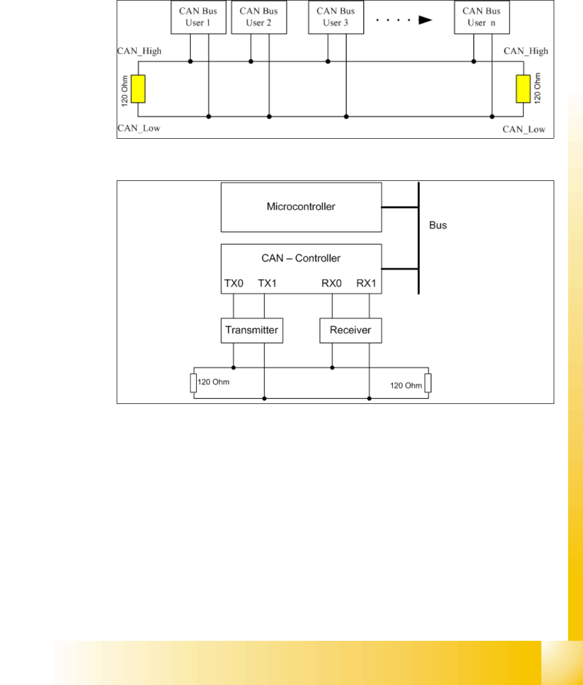
2.2.1 General structure
The CAN Bus is a decentral multi-master bus. The data are transmitted via the differential voltage
of the two CAN_High and CAN_Low lines, which are each fitted with a terminating resistance of
120 Ohm.
Fig. 2.2 - 3 CAN Bus structure
Fig. 2.2 - 4 CAN Bus -Controller and Microcontroller
Legend
– Microcontroller: Exchanges data with the CAN controller
– CAN controller: Adds the data frame, establishes the connection and manages errors.
– Transmitter/receiver: Adjusts the level (driver levels)
Each bus node has a CAN controller, which can transmit and receive data if the bus is free.
This CAN controller communicates with a microcontroller. The microcontroller steers and controls
the relevant CAN bus nodes.
A CAN Bus node can only transmit if the bus is free i.e. if there is no communication taking place
with other nodes. Access to the CAN BUS is fixed in the CAN protocol (identifier). This results in
differing priorities among the individual CAN bus nodes.