CAN Bus Workshop_Version 03__06-2008_EN.pdf - 第261页
1 - 53 Siplace C AN T est B ox Edition 04 /2008 1 CAN T est Box 53 1.10.8 Overview of CAN Bus S tructures f or X-serie s Abb. 1.10 - 30 Kabel für Axis unit Version 04 X-ser ie X2 X3 X4 Vari an t 1 Variant 2 Vari ant 1 Va…
1 - 52
Siplace CAN Test Box
1 CAN Test Box Edition 04/2008
52
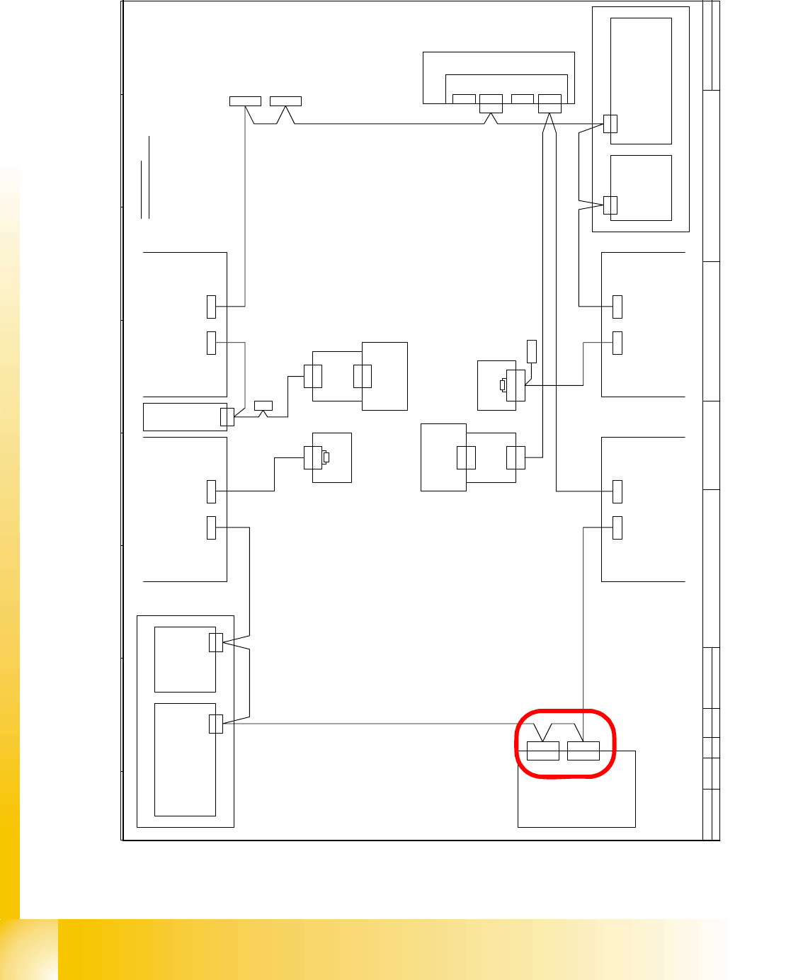
Axis unit version 04 with two connectors for the CAN Bus cable, but there is only one machine
CAN Bus cable from the machine, so we need the additional CAN Bus cable to connect the se-
cond connector for the Axis unit version 04.
D a t e
A u t h o r
D e s i g n e r
S i e m e n s A G
L & A
I t e m n a m e / B e n e n n u n g
1 4 . 1 1 . 2 0 0 1
T e k i n
G r u n d m o d u l S I P L A C E H F
T e k2 7 . 0 7 . 0 54 0 1 8 9 2
T e k0 1 . 0 9 . 0 54 0 2 0 0 6
V i s i o n C o n t r o l - U n i t
0 0 3 6 3 9 6 1 ( q d )
C A N
M a i n D i s t r i b u t o r
0 3 0 1 0 0 0 4 ( q a )
X 2 q d
X 2 q d
E i n z u g 2 E i n z u g 1
X 1 2 5X 1 2 6
C A N - I nC A N - O u t
X 1 1 5X 1 1 6
C A N - I nC A N - O u t
C A N
L P - S t e u e r u n g
X 2 2 a o
X 2 2 a o
C A N I / O - M o d u l 0 0 3 5 5 0 5 1 ( q b )
B u
S tB uS t
B u
0 3 0 1 0 0 5 0
C A N
0 3 0 1 0 0 5 1
X 2 r d
X 1 4 5
C A N - I n
B uB u
A x i s U n i t
0 3 0 1 6 1 1 0
X 3 0 _ 2 s q
C A N
E i n z u g 3
X 1 3 6
C A N - O u t
X 4 0 c a
C A N
S t
X 2 r d
C A N
S u b D i s t r i b u t o r
0 3 0 1 0 0 0 5 ( r a )
V i s i o n C o n t r o l - U n i t
0 0 3 6 3 9 6 1 ( r d )
E i n z u g 4
( c a )
S c h l e p p I n t e r f a c e
0 3 0 1 0 6 1 2
P 3
0 3 0 1 0 0 5 4
C o m p u t e r U n i t
X 1 3 5
C A N - I n
B u
B u
X 6 8
U m g e b u n g s d r u c k s e n s o r
P n e u m a t i k e i n h e i t
B e s t ü c k b e r e i c h 2
B e s t ü c k b e r e i c h 1
C A N - B u s A d e r b e l e g u n g
A d e r N r . B e l e g u n g S u b - D - P I N
1 " 1 - W i r e " 1
2 G N D 6
3 C A N _ L 2
4 C A N _ H 7
5 G N D 3
6 R E S E T 8
7 P o w e r F a i l 4
8 f r e i 9
9 C A N _ I N T 5
C A N
X 3 0 _ 2 s q
X 3 0 _ 1 s q
B u
X 3 0 _ 1 s q
B u
X 3 0 _ 2 t q
B u
X 3 0 _ 1 t q
X 1 4 6
C A N - O u t
S t
C A N I / O - M o d u l 0 0 3 5 5 0 5 1 ( r b )
X 4 0 a a
( a a )
S c h l e p p I n t e r f a c e
0 3 0 1 0 6 1 2
P 1
0 3 0 1 0 0 5 9
X 4 0 c a
B u
X 4 0 b a
B u
0 3 0 1 0 0 5 3
B u
B u
X 4 0 a a
B u
B u
B u
X 1 r b
X 1 q b
0 3 0 0 2 1 1 0
X 6 p n
X 6 p n
K o m m u n i k a t i o n s b a u g r u p p e
X 7 p nX 1 2 p n
f r e if r e i
X 1 1 p n
X 1 1 p n
C A N - B U S 1C A N - B U S 2
S t
1 2 0 O h m
A b s c h l u s s w i d e r s t a n d
0 3 0 2 7 6 4 6
X 1
1 2 0 O h m
A b s c h l u s s w i d e r s t a n d
0 3 0 2 7 6 4 6
X 1
S t
0 3 0 1 0 0 5 2
X 3 0 _ 1 s q
B u
f r e i
X 2 h e
X 1 h e
1 - W i r e H u b
0 3 0 1 0 5 7 7 ( h e )
X 2 h e
X 1 h e
1 - W i r e H u b
0 3 0 1 0 5 7 7 ( h e )
X 4 0 d a
C A N
X 1 q b
C A N
X 1 r b
1 - 53
Siplace CAN Test Box
Edition 04/2008 1 CAN Test Box
53
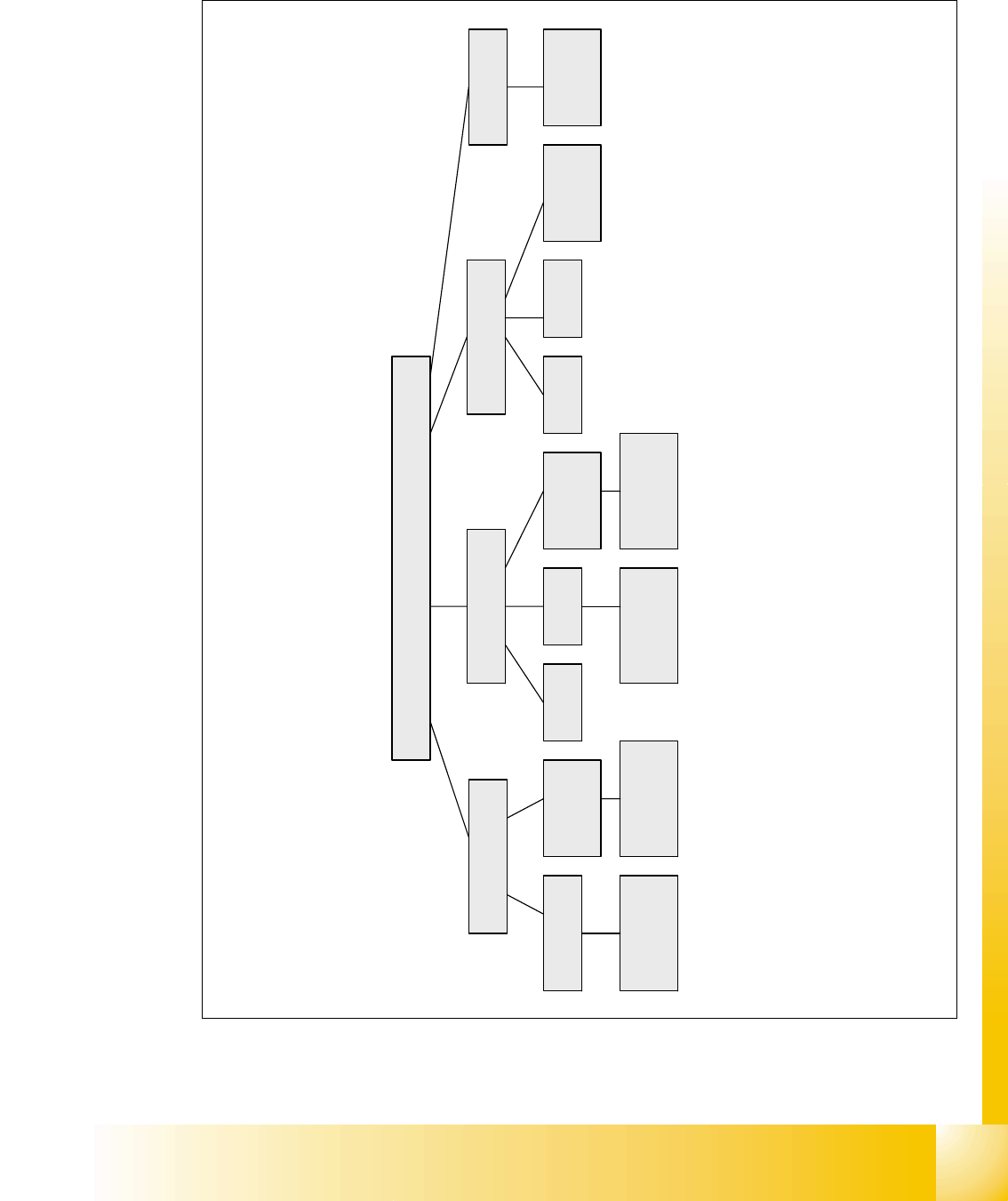
1.10.8 Overview of CAN Bus Structures for X-series
Abb. 1.10 - 30 Kabel für Axis unit Version 04
X-serie
X2
X3 X4
Variant 1 Variant 2 Variant 1 Variant 2Only Variant 2
Variant 3
with CAN
Node
Variant 3 and
WPC 4
Variant 3 and
WPC 4
X4I
Variant 3
with CAN
Node
Variant 3
with CAN
Node
Variant 3
with CAN
Node
Variant 2 and
WPC 4
Variant 2 and
WPC 4
1 - 54
Siplace CAN Test Box
1 CAN Test Box Edition 04/2008
54
1.10.9 CAN Bus Structure for Siplace X Machines
Attention: CAN bus structure!
There are two operation diagrams: 00194418-02.pdf and 00194418-01.pdf.
Always use operation diagram 00194418-02 for X2 machines or 00195280-01.The differences be-
tween this two circuit diagrams is only the introduction of the Box PC and A364.
For X3 and X4 machines, either one of the two operation diagrams may be used for the CAN bus
structure.
The CAN bus terminating resistors are located near gantries on which a C&P head is installed on
the head interface (C500). Gantries with a Twin Head will have a terminating resistor directly in-
stalled on the adapter board.
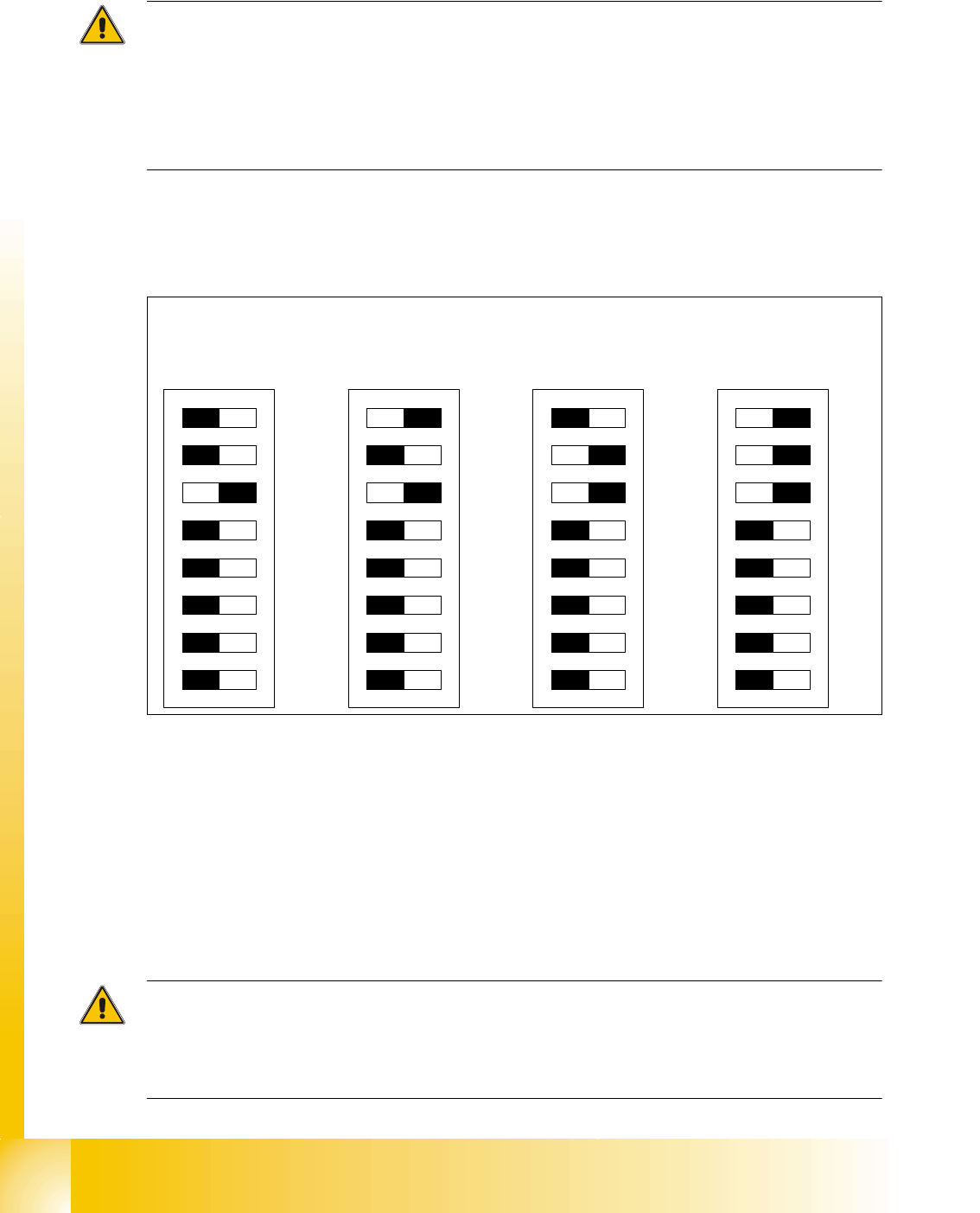
DIP switches configuration on the head interface (C500) with C&P heads
Key for DIP switches
Attention:
When using Head Modularity make sure that the terminating CAN resistor is set correctly. That
means, at the C&P heads switch CAN-Terminator ON and at the TWIN heads switch it OFF.(DIP
switch 3).
(1) P0 - Gantry address switch 1 (2) P1 - Gantry address switch 2
(3) CAN R - CAN terminator
(At TWIN-option always OFF)
(4) Boot - CAN Processor 16 Bit not mounted
(5) Reset - CAN Processor 16 Bit not mounted (6) C0 - CAN Address switch
(7) C1 - CAN Address switch (8) WPE - Write protect enable at the moment
OFF
DIP Switch
ON
78123456
ON
78123456
ON
78123456
ON
78123456
Ganty 1 Gantry 2 Gantry 3 Gantry 4