CAN Bus Workshop_Version 03__06-2008_EN.pdf - 第18页
1 - 10 S tudent Gu ide CAN BUS Wor kshop 1 Operat iona l safety Editi on 06/2 008 10 1.3 Safety equipment 1.3.1 Switches and buttons on the placement mac hine 1.3.1.1 Pos ition of switches and b uttons on the placement m…
1 - 9
Student Guide CAN BUS Workshop
Edition 06/2008 1 Operational safety
9
1.2.3 Safety instructions for the TwinHead vision modules
WARNING RISK OF HEAD CRASH 1
When the placement head is changed from the TwinHead to the Collect&Place head, the Twin-
Head's fine-pitch and flip-chip vision modules must be removed, otherwise the Collect&Place
head will collide with the module housings.
1.2.4 Safety instructions for moving the component trolley
WARNING 1
To prevent accidents, ALWAYS follow the rules listed below when you move the component trol-
ley.
➠ Always hold the handles with both hands when you want to move the component trolley.
➠ Remember that a component trolley with the full complement of feeders can tip over sideways
or forward on gradients of 20° or more.
➠ Make sure that the surface on which the trolley is moved has a significantly smaller gradient.
➠ Be careful not to collide with obstacles. The trolley could tip forward if it is traveling fast enough.
1 - 10
Student Guide CAN BUS Workshop
1 Operational safety Edition 06/2008
10
1.3 Safety equipment
1.3.1 Switches and buttons on the placement machine
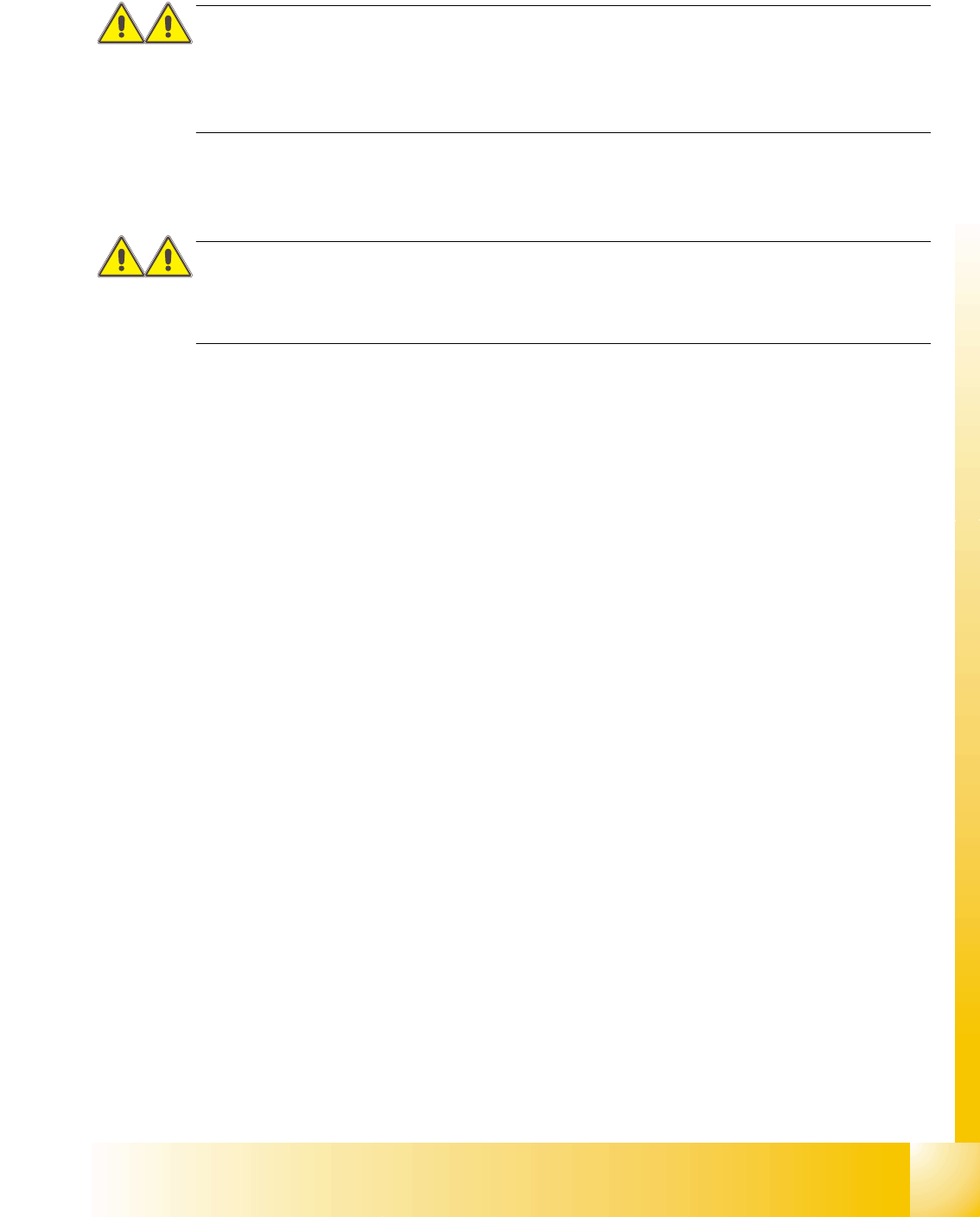
1.3.1.1 Position of switches and buttons on the placement machine
Fig. 1.3 - 1 Position of switches and buttons - View of the PCB output side
1. Main power switch
2. Stop button (black) on the operator panel on the power supply side
3. Start button (white) on the operator panel on the power supply side
4. Component counter on the operator panel on the power supply side
5. Emergency stop push-button on the output side
6. Start button (white) on the output side
7. Stop button (white) on the output side
8. Service socket in the power supply unit behind the cover
(T) PCB transport direction
1 - 11
Student Guide CAN BUS Workshop
Edition 06/2008 1 Operational safety
11
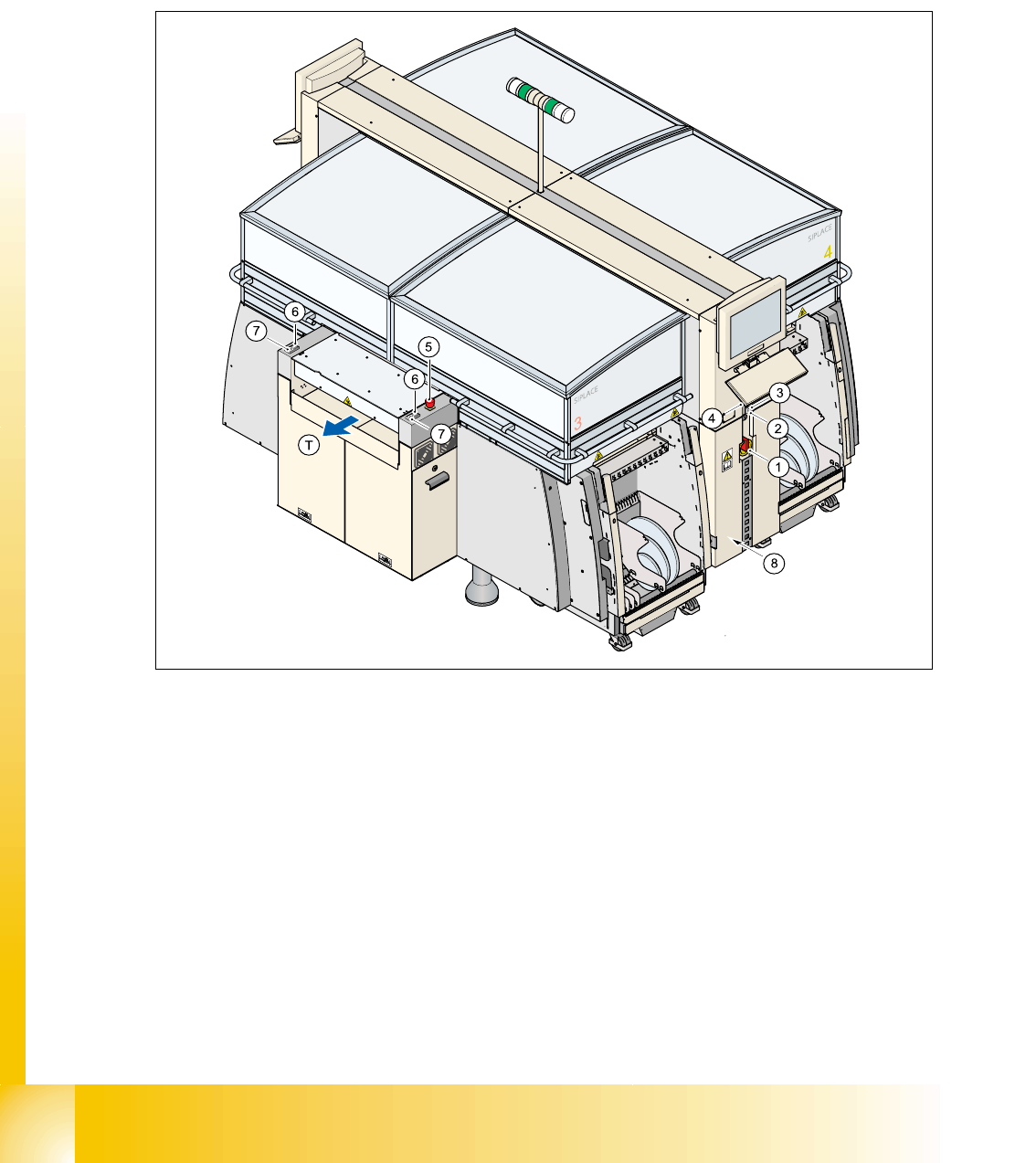
1.3.1.2 Position of protective switches on the placement machine
Fig. 1.3 - 2 Position of protective switches on the placement machine
1. Protective cover switch, location 1
2. Protective cover switch, location 2
3. Protective cover switch, location 3
4. Protective cover switch, location 4
5. Protective switch for the cover on the input side of the PCB conveyor
6. Protective switch for the cover on the output side of the PCB conveyor
(T) PCB transport direction