CAN Bus Workshop_Version 03__06-2008_EN.pdf - 第22页
1 - 14 S tudent Gu ide CAN BUS Wor kshop 1 Operat iona l safety Editi on 06/2 008 14 1.3.3 Safety circuit and signaling circuit 1.3.3.1 Des cription of t he funct ions of the safety circuit The foll owing con dition s mu…
1 - 13
Student Guide CAN BUS Workshop
Edition 06/2008 1 Operational safety
13
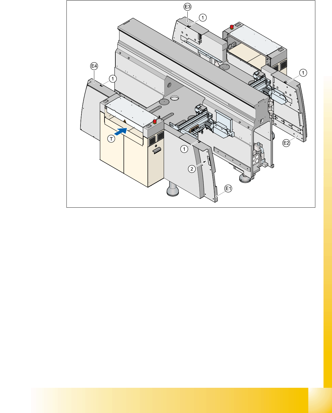
1.3.2 Position of the push-buttons for docking the component trolleys in and out
Fig. 1.3 - 3 Position of push-buttons on the component trolley
1. Push-button on the top
2. Push-button in the guard
E1guard, location 1
E2guard, location 2
E3guard, location 3
E4guard, location 4
Two push-buttons are integrated into the guard module (items E1, E2, E3 and E4). These are used
to dock the component trolley in or out at the location. These push-buttons must be pressed si-
multaneously, if you docking the component trolley.

1 - 14
Student Guide CAN BUS Workshop
1 Operational safety Edition 06/2008
14
1.3.3 Safety circuit and signaling circuit
1.3.3.1 Description of the functions of the safety circuit
The following conditions must be fulfilled in order to start and operate the placement machine:
– all four component trolleys must be docked in and connected.
– all covers - four over the gantries, one over the PCB input belt and one over the output belt -
must be closed.
– both emergency stop push-buttons must be released.
– the cover flaps (option) over the feeders must be closed.
– the minimum operating pressure must have been reached.
– the "software enable" signal must be active. This ensures that the safety circuit is closed.
– the power supply must be sending 24 V to the Start buttons and the protective contactor com-
bination.
– If one of the Start buttons is now pressed, the protective contactor combination PCC K6 will
switch and activate the following components:
– 250 VDC link voltage for the servo amplifiers for the gantry axes
– 145 VDC link voltage for the star axes
– the axis unit receives a "Servo Enable" signal for the servo amplifier
– 34 VDC operating voltage is switched to the component trolleys.
– 24 VDC operating voltage is switched to the used tape cutters.
– the PCB conveyor control receives the enable signal for the PCB clamping, the PCB stop-
per and the lifting table control.
The machine is then ready for use.
1 - 15
Student Guide CAN BUS Workshop
Edition 06/2008 1 Operational safety
15
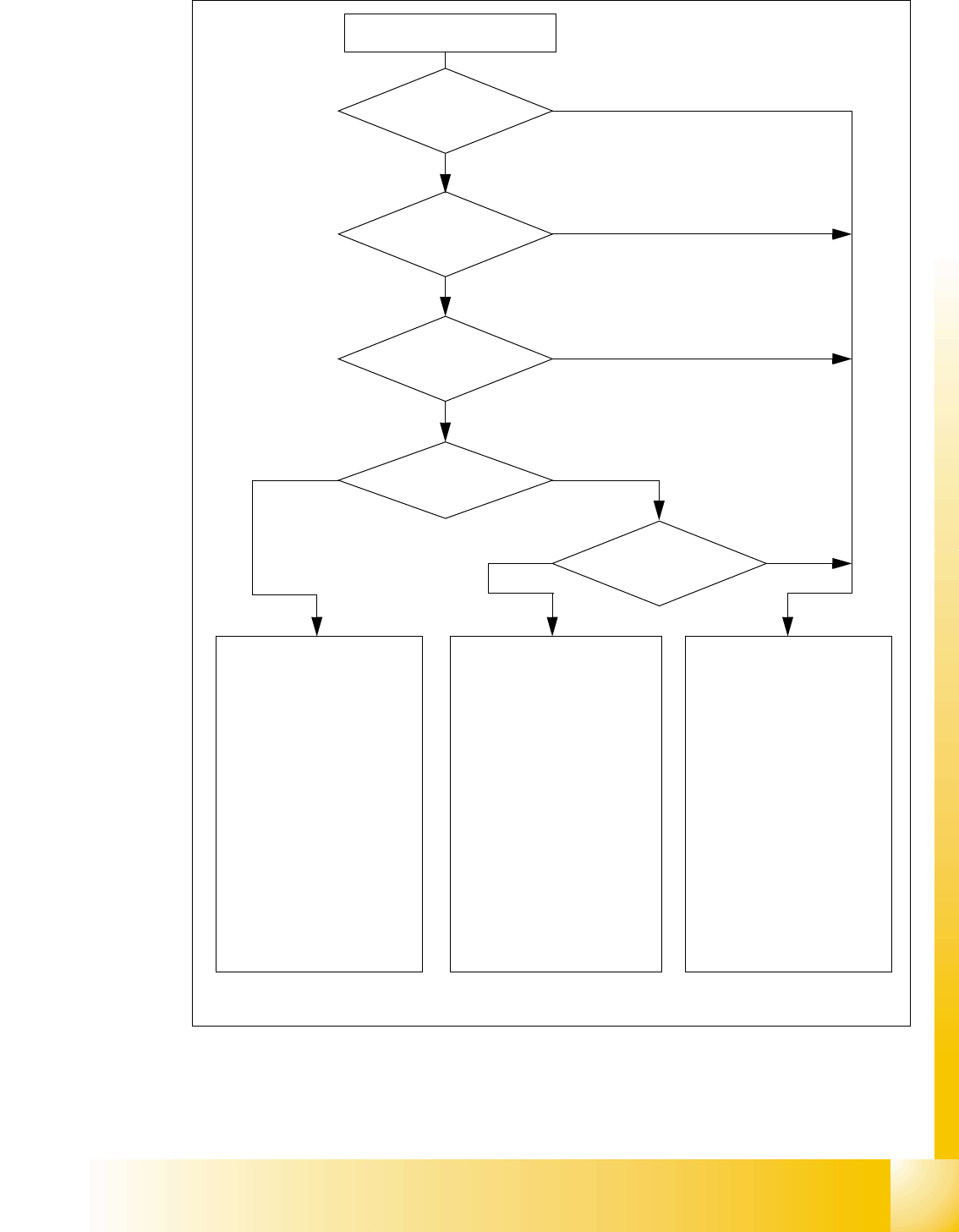
Fig. 1.3 - 4 Safety circuits
Start button pressed
Compressed air
min. 0.5 MPa
(5.0 bar)?
No
Emerg. stop
push-button pressed?
Protective cover open ?
Safety mode
activated on the user
interface?
No
Component
trolley safety circuit
interrupted?
Yes
No
No
Yes
Yes
No
Active
PCC*) Yes
Voltage
Y axis 250 V-
X axis 250 V-
star axis 145 V-
DP axis/D-Twin 40 V-
Z axis/Z-Twin 40 V-
Active
PCB conveyor Yes
Lifting table Yes
PCB clamping Yes
Width adjustment Yes
Laser light barrier Yes
Tape cutter Yes
CO trolley dock. unit Yes
Yes
Active
PCC*) No
Voltage
Y axis 0 V
X axis 0 V
star axis 0 V-
DP axis/D-Twin 40 V-
Z axis/Z-Twin 40 V-
Active
PCB conveyor Yes
Lifting table No
PCB clamping No
Width adjustment Yes
Laser light barrier No
Tape cutter No
CO trolley dock. unit Yes
Active
PCC*) No
Voltage
Y axis 0 V
X axis 0 V
star axis 0 V-
DP axis/D-Twin 40 V-
Z axis/Z-Twin 40 V-
Active
PCB conveyor No
Lifting table No
PCB clamping No
Width adjustment No
Laser light barrier No
Tape cutter No
CO trolley dock. unit No
*) PCC protective contactor combination K6
Yes
Start button pressed