CAN Bus Workshop_Version 03__06-2008_EN.pdf - 第219页
1 - 1 1 Siplace C AN T est B ox Edition 04 /2008 1 CAN T est Box 11 1.8 Ch ecking the CAN Bus for Erro r Frames Wha t are e rror fra mes ? Error fr ames ar e sen t by t he indiv idual su bsyste ms, whe n a co mmand does …
1 - 10
Siplace CAN Test Box
1 CAN Test Box Edition 04/2008
10
Step by step: 1
➠ Connect the CAN Test Box to the service plug (Note: Not all signals on the Service plug) of the
COM assembly.
➠ Connect the oscilloscope to the BNC sockets CAN_H and CAN_L.
➠ Set the measurement range for channels 1 and 2 to 1V and the sweep to 2μs
(see Fig. 1.7 - 3) and the trigger to channel 1.
➠ Switch the machine on and wait until it has booted.
➠ When the machine is in idle mode, position the signals on the oscilloscope into the center of
the screen.
➠ To simulate CAN bus communication, you can start a version query in Sitest or Caccia.
➠ Press the Stop button on the oscilloscope.
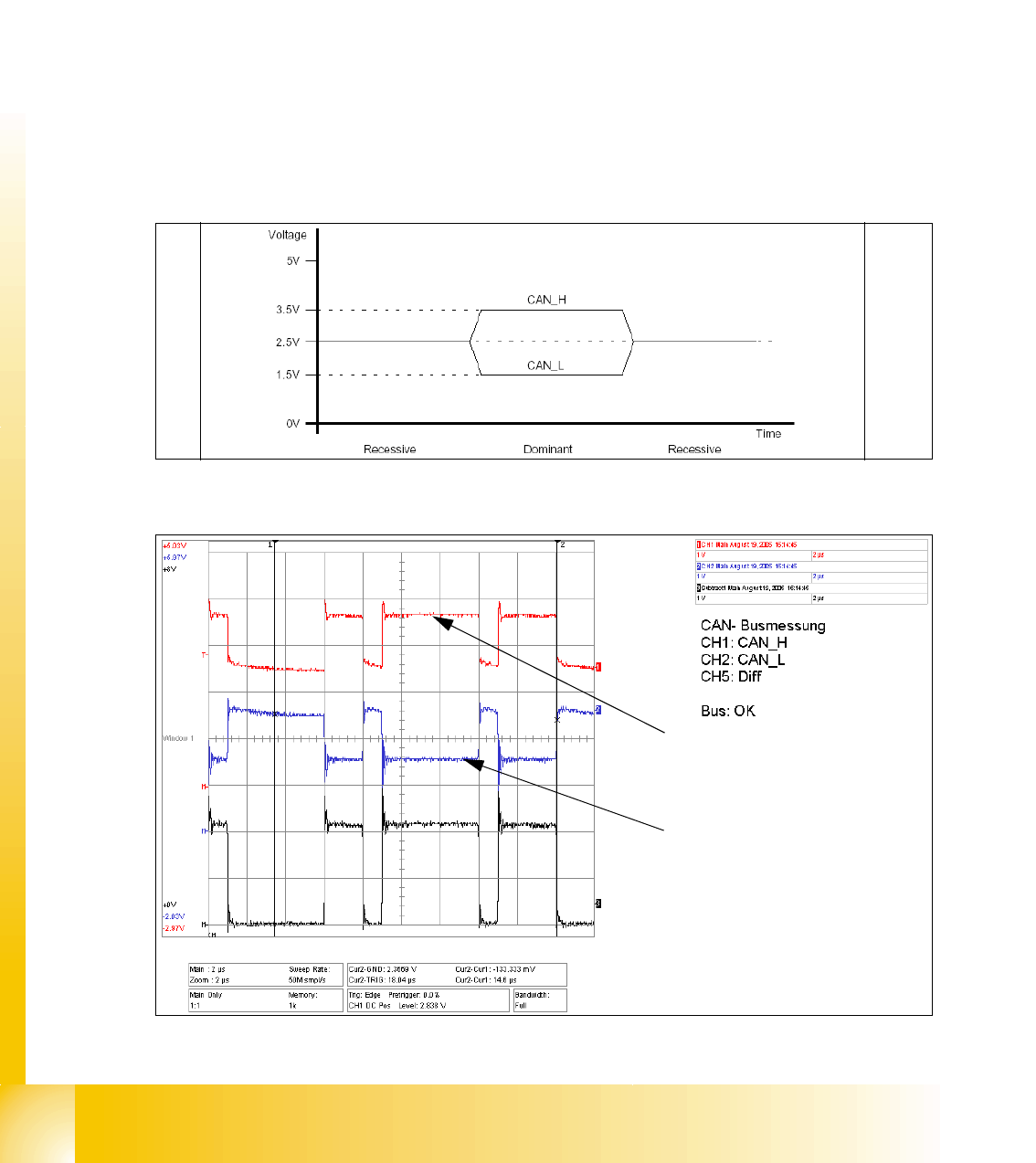
➠ You can now check the signal voltage levels. You should receive a value of 3.5V ( 2.75 - 4.5V)
for CAN_H and of 1.5V (2.0 - 1.0V) for CAN_L .
Fig. 1.7 - 2 Theoretical representation of recessive and dominant CAN_H and CAN_L signals
Fig. 1.7 - 3 Recessive and dominant CAN_H and CAN_L signal
Dominant CAN_H signal
Dominant CAN_L signal
1 - 11
Siplace CAN Test Box
Edition 04/2008 1 CAN Test Box
11
1.8 Checking the CAN Bus for Error Frames
What are error frames?
Error frames are sent by the individual subsystems, when a command does not adhere to the en-
coding rules or has been physically corrupted.
This occurs when a CAN telegram shows the same RxD level (low) for 6 or more consecutive bits
(logic 0 = dominant).
If a subsystem recognizes this type of command, it will immediately notify all other subsystems
and the transmitter of the telegram, by sending error frames.
After receiving an error frame, the other subsystems will reject the message (telegram) sent and
send their own error frames. Once the bus is free again, the command will be resent.
The CAN Test Box is used to check the CAN network for error frames.
Note: When switching the machine on and off, the CAN Test Box will recognize any error frames.
This means that the Error Frame Counter have to reset after each reboot manually.
Step by step: 1
➠ Connect the CAN Test Box to the service plug (Note: Not all signals on the Service plug) of the
COM assembly.
➠ Switch the machine on and start the placement program.
➠ During production, the CAN Test Box can remain connected, even with the oscilloscope. The
trigger input should be connected to the BNC socket error frame of the CAN Test Box.
➠ The number of error frames can be seen on the counter. An accumulation of error frames in-
dicates possible physical bus errors.
If too many error frames are recognized during operation, you will need to analyze the CAN
signals in detail.
Guideline value: Number of error frames during 4h placement operation < 10
1 - 12
Siplace CAN Test Box
1 CAN Test Box Edition 04/2008
12
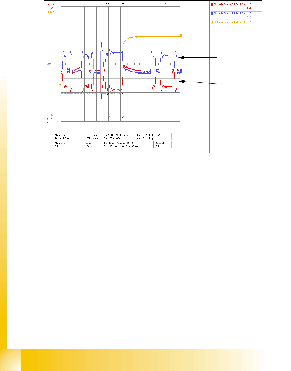
Fig. 1.8 - 1 CAN telegram with error frame
The Error Frame Counter switches, since one block of the CAN telegram (6 bits in this case) has
maintained the same state for approx.6μs. For a 1MBit bus, 1 bit has a length of 1μs, resulting in
a max. block length at the same level of 5μs.
The CAN Test Box Error Frame Counter is preset and counts 1 Mbit CAN bus at 5.5μs. 500KBaud
CAN bus HS60 is counted at 11μs.
These settings of 5.5μs and 11μs are factory set in the CAN Test Box with the help of a potenti-
ometer.
5.9μs
CAN _H level
CAN _L level