CAN Bus Workshop_Version 03__06-2008_EN.pdf - 第38页
1 - 12 S tudent Gu ide CAN BUS Wor kshop 2 Commun icatio n and C ontrol Editio n 06/200 8 12 2.2.3 CAN Bus Concept Sip lace X4I Note : For the Siplace X4I an d only with th e SW 7 0x, ther e is only one station compu ter…
1 - 11
Student Guide CAN BUS Workshop
Edition 06/2008 2 Communication and Control
11
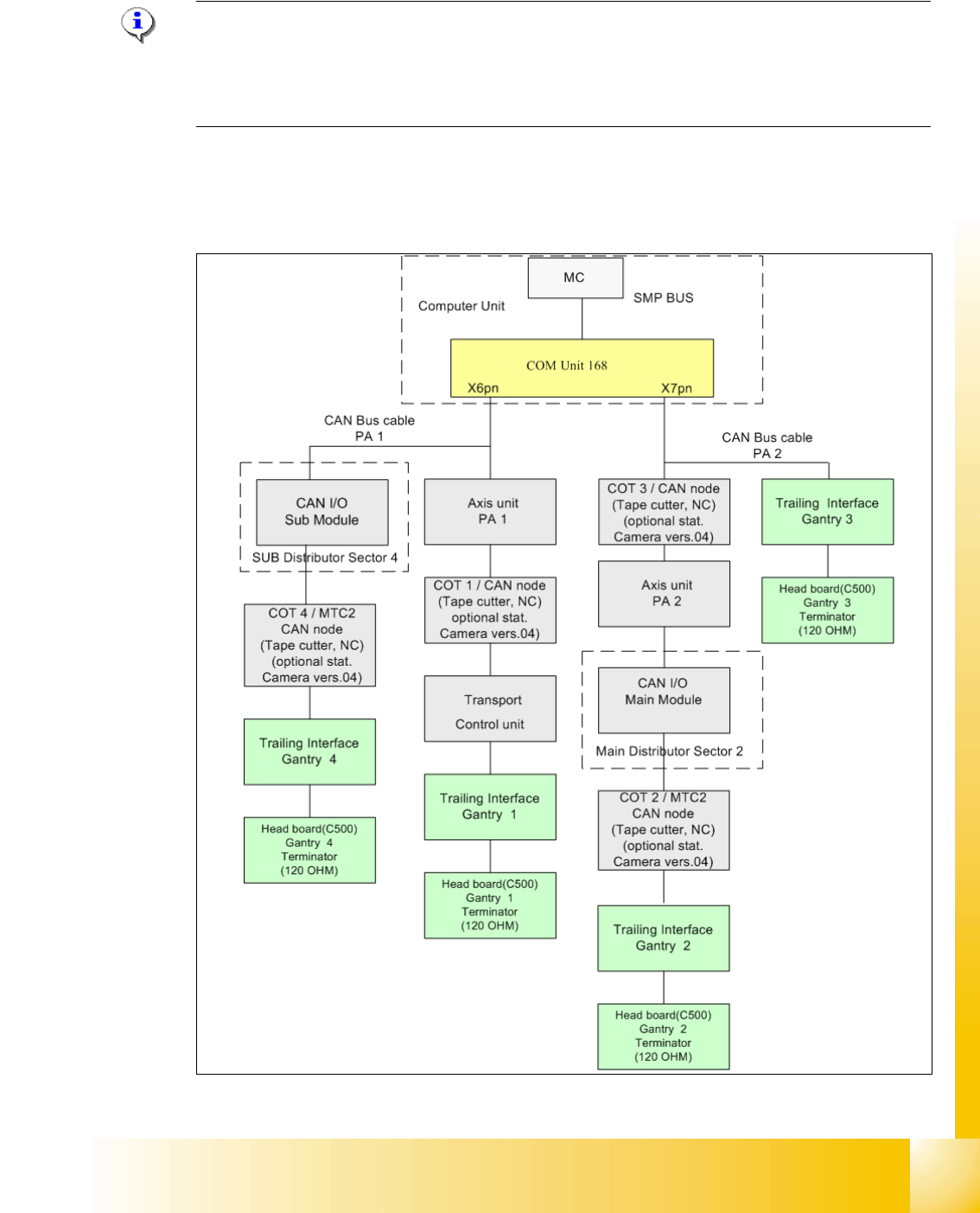
2.2.2 CAN Bus Concept Siplace X4
Note: In SIPLACE X machines, the machine controller is a box PC. This also contains the COM
unit. From approx. 2008 machines will not have separate illumination control as this is realized in
the stationary cameras from version 4 onwards. The NCs are addressed and the sensors moni-
tored by the CAN node module. The NC is therefore reintegrated into the CAN bus system.
The placement machine SIPLACE X uses a bus system with 1 Mbit/s transmission rate.The CAN:
Bus system begin at the Communication board and is split in 2 path. Every path is terminated by
a 120 ohm terminator on the head board at the individual placement head.
Fig. 2.2 - 9 CAN Bus overview Siplace X4
1 - 12
Student Guide CAN BUS Workshop
2 Communication and Control Edition 06/2008
12
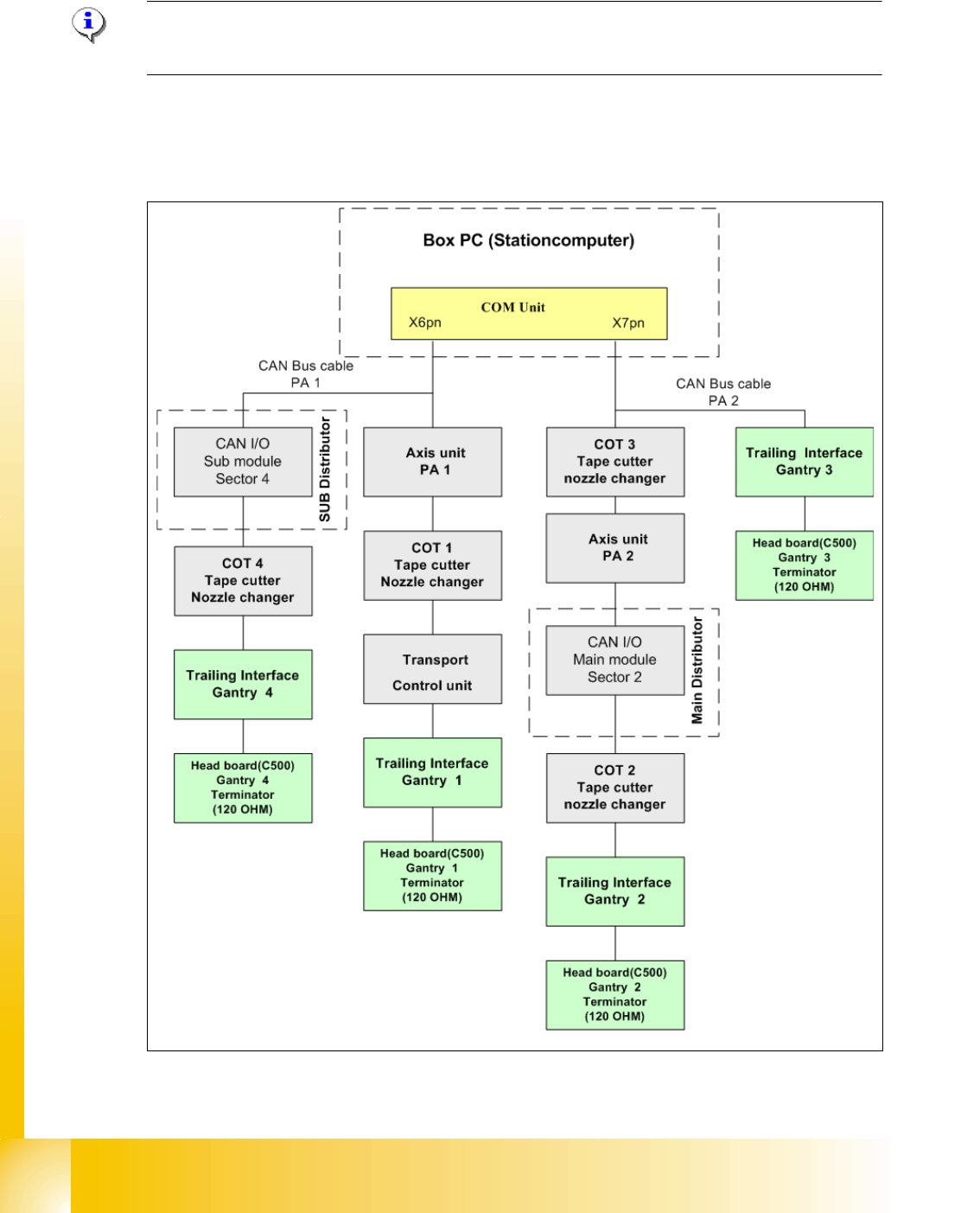
2.2.3 CAN Bus Concept Siplace X4I
Note: For the Siplace X4I and only with the SW 70x, there is only one station computer, which
assumes control of the entire machine.
The placement machine SIPLACE X4I uses a bus system with 1 Mbit/s transmission rate.The
CAN: Bus system begin at the Communication board and is split in 2 path. Every path is termi-
nated by a 120 ohm terminator on the head board at the individual placement head.
Fig. 2.2 - 10 CAN Bus overview Siplace X4I
1 - 13
Student Guide CAN BUS Workshop
Edition 06/2008 2 Communication and Control
13
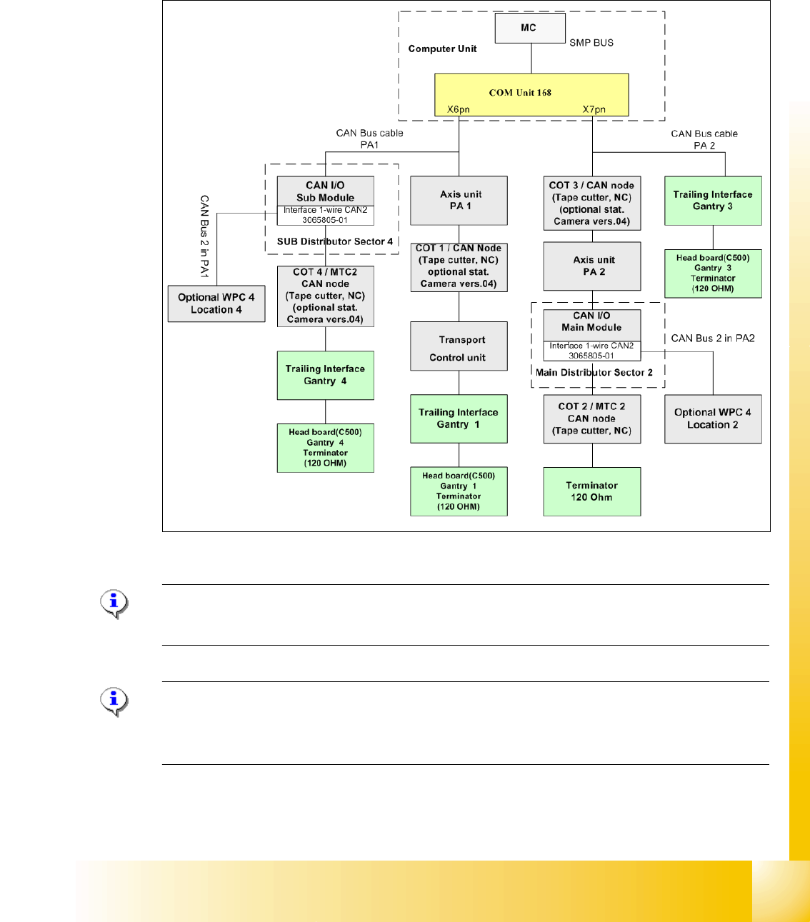
2.2.4 CAN Bus Concept SiplaceX3
The placement machine SIPLACE X3 uses a bus system with 1 Mbit/s transmission rate.The CAN
Bus system begin at the Communication board and is split in 2 path. Every path is terminated by
a 120 ohm terminator on the head board at the individual placement head.
.
Fig. 2.2 - 11 CAN Bus overview Siplace X3
Note: When the Twin head is mounted, the switch for the terminator on the head board (C500)
have to be OFF. 2
Note: From SW 605 the WPC4 will be offered as an option for the X2 and X3. This option requires
thenew "Interface 1-Wire CAN2". The WPC is then controlled via the CAN2.When the Twin head
is mounted