CAN Bus Workshop_Version 03__06-2008_EN.pdf - 第184页
1 Caccia Student Guide CACCIA Manual Issue 04/2007 EN 92 (4) Answer initialization successful. Allocation of subsystems to th e hardware component s e.g. Siplace X P A1 PPW --> Nozzle changer (NC) Subsystem Hardware c…
CACCIA Manual 1 Caccia Student Guide
Issue 04/2007 EN
91
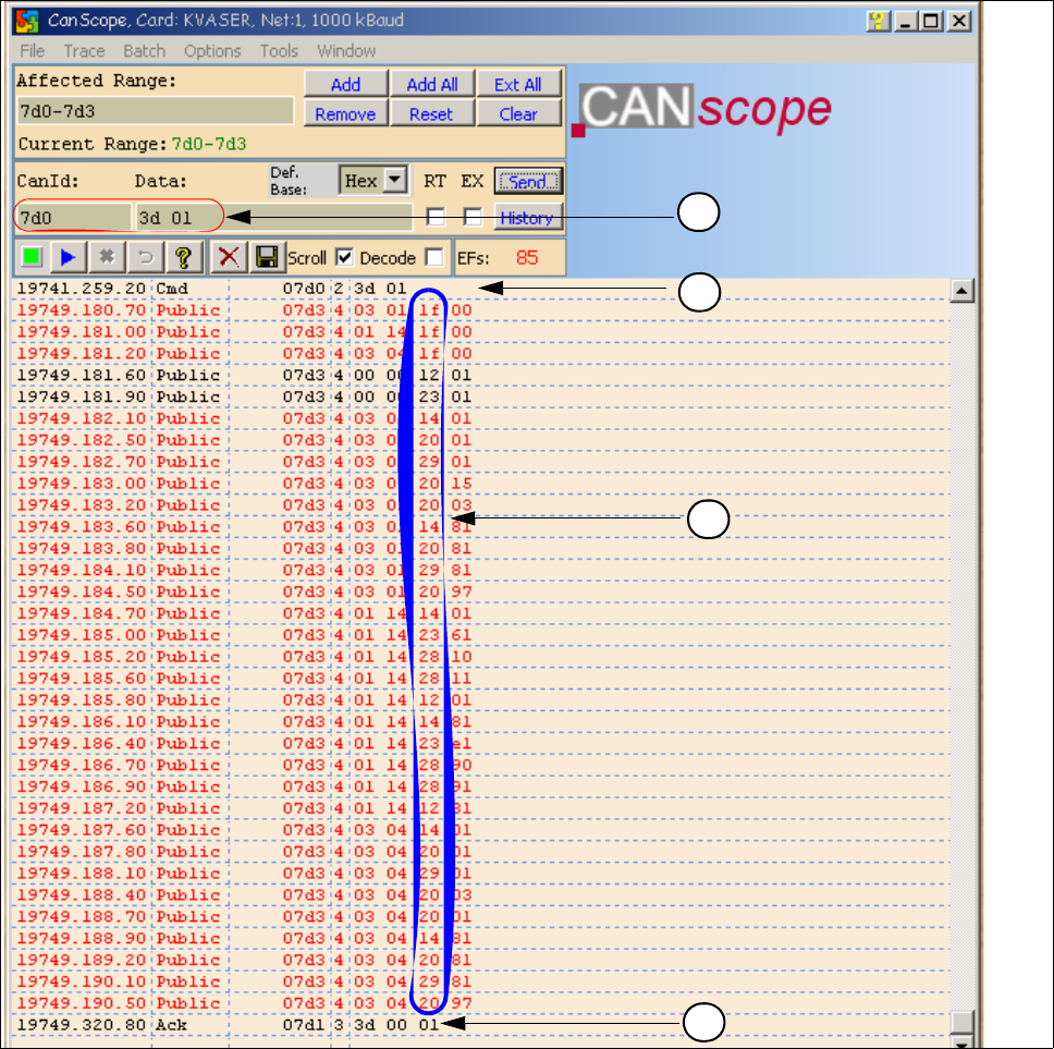
1.11.3.2 Overview Initialization of the One Wire Bus
(1) CAN BUS command for initialization
(2) CAN BUS command sent.
(3) Subsystems give a message via the public bytes
1f --> Coupler 12 --> I/O component with EEPROM 14 --> 1k EEPROM
20 --> 4 channel A/D 23 --> 4k EEPROM 28 --> Temperature
29 --> 8 x I/O component
1
2
4
3

1 Caccia Student Guide CACCIA Manual
Issue 04/2007 EN
92
(4) Answer initialization successful.
Allocation of subsystems to the hardware components
e.g. Siplace X PA1
PPW --> Nozzle changer (NC)
Subsystem Hardware components Notes
PPW, 1, Coupler, 00 RS232 Interface on the I/O
module
Temperatur, 20, Coupler, 00
RS232 Interface on the I/O
module
PPW, 4, Coupler, 00 RS232 Interface on the I/O
module
Mainpath, 0, IO_2C, 01
Mainpath, 0, E2_512B, 01
RS232 Interface on the I/O
module
RS232 Interface board will be integrated
in the I/O module later.
Temperatur, 20, E2_32B, 01
Temperatur, 20, E2_512B, 61
Temperatur, 20, Temperatur, 10
Temperatur, 20, Temperatur, 11
Temperatur, 1, IO_2C,01
Temperature sensors
Gantry 1
The two temperature sensors form a unit
and can only be replaced as a set. The
part for the gantry recognition can not
change.
Temperatur, 20, E2_32B, 81
Temperatur, 20, E2_512B, e1
Temperatur, 20, Temperatur, 90
Temperatur, 20, Temperatur, 91
Temperatur, 20, IO_2C,81
Temperature sensors
Gantry 4
The two temperature sensors form a unit
and can only be replaced as a set. The
part for the gantry recognition can not
change.
PPW, 4, AD, 03
PPW, 4, AD, 01
PPW, 4, AD, 81
1 Wire Hub NC on location 4 Shows, that the 1 Wire Hub is connected .
PPW, 4, E2_32B, 01
PPW, 4, IO_8C, 01
PPW, 4, AD, 01
Control board NC Gantry 4,
only C&P20 NC
Control board of NC row 1
(only C&P 20 NC).
PPW, 4, E2_32B, 81
PPW, 4, IO_8C, 81
PPW, 4, AD, 97
Control board NC Gantry 4,
only C&P20 NC
Control board of NC row 2
(only C&P 20 NC).
PPW, 1, AD, 01
PPW, 1, AD, 03
PPW, 1, AD, 81
1 Wire Hub NC on location1 Shows, that the 1 Wire Hub is connected.
PPW, 1, E2_32B, 01
PPW, 1, IO_8C, 01
PPW,1 AD, 15
Control board NC Gantry 1,
only C&P20 NC
Control board of NC row 1
(only C&P 20 NC).
PPW, 1, E2_32B, 81
PPW, 1, IO_8C, 81
PPW, 1, AD, 97
Control board NC Gantry 1,
only C&P20 NC
Control board of NC row 2
(only C&P 20 NC).
CACCIA Manual 1 Caccia Student Guide
Issue 04/2007 EN
93
1.12 Board type recognition
1.12.1 What does it mean board type recognition?
Don‘t confused the board type recognition with the option recognition of the PCB Barcode.
The board type recognition is an ID (identification number), which is saved in an EEPROM. These
ID‘s identify the boards (head interface, headadapter,...) in the machine via software. The recog-
nition will be carried out on each PCB which is controlled by the TQM modules and the PCB‘s in
which the TQM module are installed. The board type recognition is carryed out on the BIOS (Ver-
sion 3.C0 or higher) of the TQM Module. These board type ID will be read and checked from the
BIOS in the TQM Module.
1.12.1.1 Why we integrate the board type recognition?
The introduction of the board type recognition has the advantage, that only one BIOS version for
all TQM modules which are installed on all machines subsystems is used.
Advantages:
– simple to use for developer, set up engineer and service engineer
– updates only for one Bios version for the developer
– spare parts one stock, only one SAP part number
The introduction of one BIOS version on the TQM Modules for the different Subsystems was
necessary for the option Head Modularity.
1.12.1.2 Functional description
During the software start up the BIOS of TQM Modules recognizes the PCB‘s ID e.g. Which PCB,
dependig on head type, is mounted or which board is the TQM module set. The station software
(with SW 601.02) will give an error message, if it does not recognize the ID or if it is not a plausible
ID. At the moment the error will be appears only on the 7 segment display of the TQM Moduls.
1.12.1.3 Error description
When the BIOS and Application software are downloaded and the BIOS is unable to recognize
one ID, it will give an error on the seven segment display for a short time. The error message ap-
pears 3 times, after that the application software starts up. The machine still starts up and can pro-
duce. If the BIOS is unable to recognize more than one ID, the TQM module in the BIOS stops
with an error code on the 7 segment display. The machine stops and an error appears. In this case
you have to look which error is displayed on the 7 segment display of the TQM module. (see error
list). So, you have to write the correct ID‘s to the board.