CAN Bus Workshop_Version 03__06-2008_EN.pdf - 第78页
1 - 16 S tudent Gu ide CAN BUS Wor kshop 3 CAN BU S Editio n 06/200 8 16 27 Da tum06/2 0 08 Versi o n 03 CAN Bus Works hop M athias Mic hel SIPL ACE Ca mp us Automation a nd Drive s 5, 9 μ s 3. Beisp iel Erro r Frames 3.…
1 - 15
Student Guide CAN BUS Workshop
Edition 06/2008 3 CAN BUS
15
25Datum06/2008 Version 03 CAN Bus Workshop Mathias Michel
SIPLACE Campus
Automation and Drives
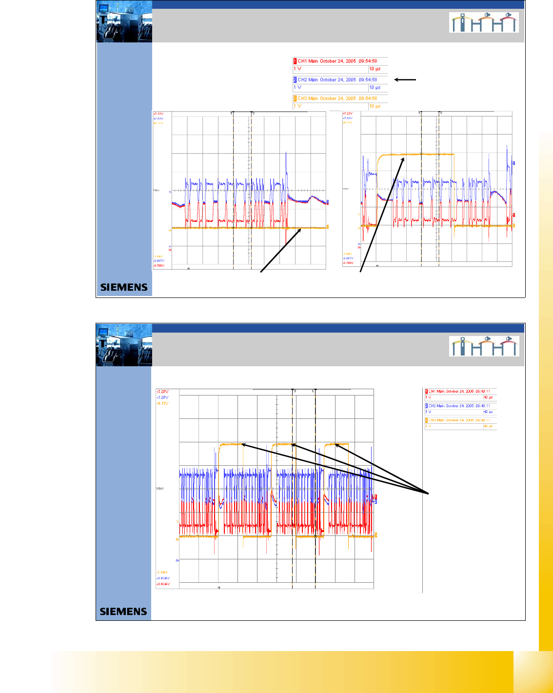
Record of CAN telegrams during placement, with aid of the CAN Test Box
Error counter (Error Frames) = 0 Error counter (Error Frames) = 1
3. Beispiel Error Frames
3. Example of Error Frames
Settings oscilloscope
26Datum06/2008 Version 03 CAN Bus Workshop Mathias Michel
SIPLACE Campus
Automation and Drives
Error counter (Error Frames) = 3
3. Beispiel Error Frames
3. Example of Error Frames
Record of CAN telegrams during placement, with aid of the CAN Test Box
1 - 16
Student Guide CAN BUS Workshop
3 CAN BUS Edition 06/2008
16
27Datum06/2008 Version 03 CAN Bus Workshop Mathias Michel
SIPLACE Campus
Automation and Drives
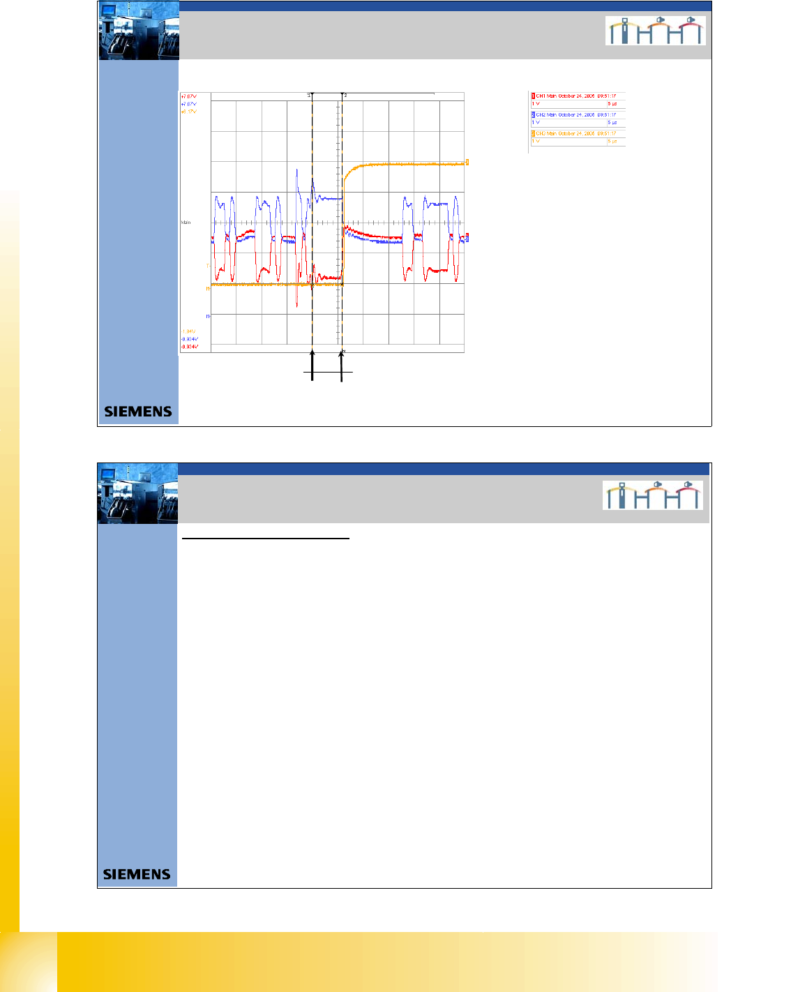
5,9μs
3. Beispiel Error Frames
3. Example of Error Frames
Record of CAN telegrams during placement, with aid of the CAN Test Box
CAN Telegram with error :
- One block contain 6 or more bits with
the same level (LOW).
-1 bitis1μs = max. lenght of a block
with the same level are 5μs.
- That mean the error counter starts
for a 1MBaud CAN Bus after 5,5μs.
- For a 500KBaud CAN Bus
e.g.HS60 after 11μs
28Datum06/2008 Version 03 CAN Bus Workshop Mathias Michel
SIPLACE Campus
Automation and Drives
3. Mögliche Fehlerquellen
Helpful tips for troubleshooting:
0. In General:
Which CAN BUS structure? Æ Station SW?, one or two CAN Bus?, Com Board?, CAN Bus cable?
Which placement area? Æ PA 1 or PA 2
Which Gantry? Æ 1,2,3,4
Which Location? Æ 1,2,3,4
Is there an MTC 2 installed? Æ Location 2 or 4?
Location Æ Tape cutter, Feeder control unit (FCU), „Nozzle changer“ ?
Gantry Æ Headinterface , Placement Head
1. The sporadic drop in voltage or a short circuit of Power Fail, CAN Init and CAN Reset to other
signals could lead to logical faults in the CAN bus system (e.g. CAN timeout)
Check the signal Power Fail, CAN Init and CAN Reset of your 5 V level (min. 4V is accept).
Should CAN bus errors occur sporadically, it may be helpful to check the signals during the
production process.
Trigger the signals and use the CAN Test Box and an oscilloscope to monitor the 5V voltages. This
helps you to determine whether the signals are really stabile and ensures that no sporadic drops in
voltage occur.
2. Lenght of the CAN Bus cable: The lenght of the CAN Bus cable determine the Baudrate.
Maximum lenght for 1Mbit/s are 40m,
for 500kBit/s are 100m
for 125kBit/s are 500m
3. Source of errors

1 - 17
Student Guide CAN BUS Workshop
Edition 06/2008 3 CAN BUS
17
29Datum06/2008 Version 03 CAN Bus Workshop Mathias Michel
SIPLACE Campus
Automation and Drives
3. Mögliche Fehlerquellen
3. The following Error message appears:
COM Unit 168: Error message CAN Card MC (COM 168) FM_CAN_FIRMWARE_VERSION
Æ 3524 Falsche CAN Firmware-Version (Info 1: Firmware-Version / Info 2: Release-Nr.)
Æ 3524 wrong CAN Firmware-Version (Info 1: Firmware-Version / Info 2: Release-Nr.)
Solution Download the correct version to the COM 168
Note: The correct firmware should be storage on the MC after you start the MC Distributor
Check the Application on the CAN COM 168 Siplace X:
• Attention please disconnect the CAN Bus cable from the COM Board and Switch ON the machine!
• Switch to the MC and change to the console with F4
• Change to drive D (cd d:)
• Change to the folder fw_dl (cd fw_dl)
• Query version enter the command D:\FW_DL >ver_c168
Download the Application on the CAN COM 168 Siplace X:
• Start the Download with the command e.g. pcidown.386 FW113.HEX
(at first search the newest application file and for help look to sc d: FW_DL unter read me .txt)
• Note: At first appears the current version
• After few seconds you see the new version on the display automatically.
• Switch OFF and ON the machine!
3. Source of errors