00191413-01.pdf - 第104页
3 Desktop (Root W indow) User Manual Line Computer UNIX 3.2 Desktop User Interface Software Version 501.xx 01/99 Issue 3 - 34 3.2.1.4 P RODUCT Menu - Component Editor Serves to open the user int erface of the Com ponent …
User Manual Line Computer UNIX 3 Desktop (Root Window)
Software Version 501.xx 01/99 Issue 3.2 Desktop User Interface
3 - 33
NOTE
The user’s name cannot be changed.
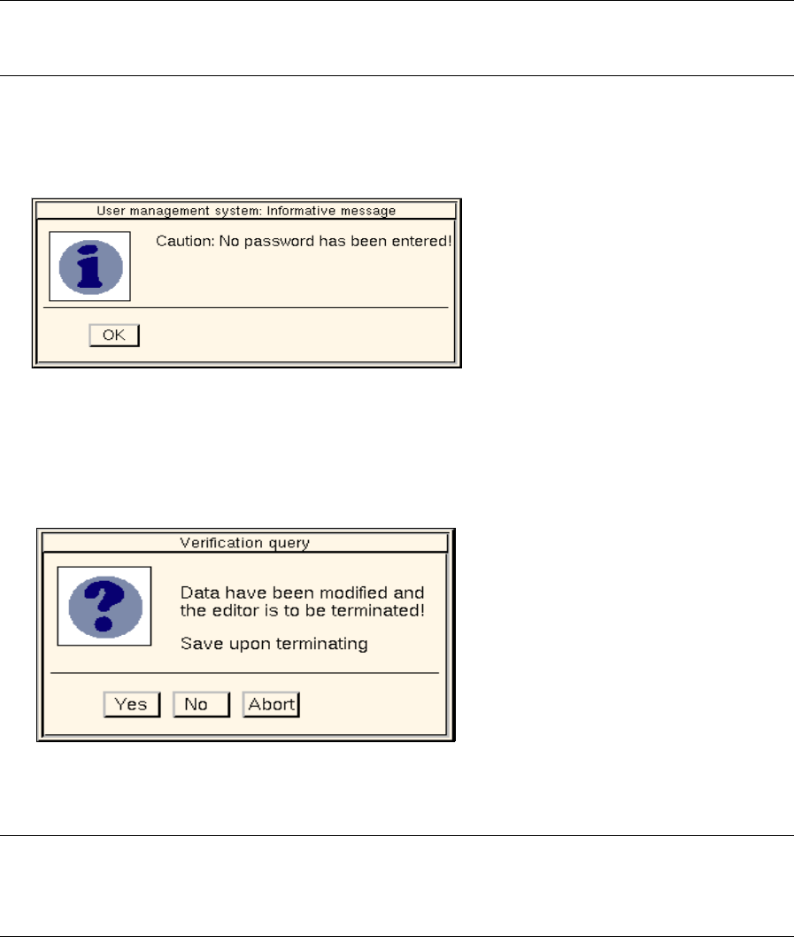
● If an existing password is to be deleted, click on the "New password" editing field and press the
RETURN key. The following dialog box opens.
● Click on OK to confirm your entry. The dialog box closes.
● Once all required entries or changes have been made, click on FILE --> Exit on the menu bar.
The following dialog box is displayed.
● Click on Yes.
The dialog box and the configuration window close.
NOTE
If no password has been specified for the user account, a message telling you that no password has
been entered will be displayed again after the configuration window has been closed (see above).
● Click on OK.
The dialog box closes.
● Click on FILE --> Exit on the menu bar of the "Administration of user accounts" dialog window
(see Fig. 3.2.1). The dialog window closes.
3 Desktop (Root Window) User Manual Line Computer UNIX
3.2 Desktop User Interface Software Version 501.xx 01/99 Issue
3 - 34
3.2.1.4 PRODUCT Menu
- Component Editor
Serves to open the user interface of the Component Editor. The Component Editor allows the user to
completely describe components in their electrical characteristics.
● Click on PRODUCT --> Component Editor.
The FSB containing the file selection of all already-defined components is opened.
NOTE The further procedure to be followed is described in chapt. 5.
- Package Form Editor
Serves to open the user interface of the Package Form Editor. The Package Form Editor allows the
user to completely describe components in their geometrical characteristics.
● Click on PRODUCT --> Package Form Editor.
The FSB containing the file selection of all already-defined package forms is opened.
NOTE The further procedure to be followed is described in chapt. 6.
- Adhesive Pattern Editor
Serves to open the user interface of the Adhesive Pattern Editor. The coordinates of adhesive dots for
adhesive patterns are defined in the Adhesive Pattern Editor. Due to the different adhesive patterns
available it can be ensured that components of various sizes can be securely attached to the PCBs
during production.
● Click on PRODUCT --> Adhesive Pattern Editor.
The FSB containing the ".dm" file is opened. This file contains all already-defined adhesive
patterns.
● Select the .dm adhesive pattern file by double-clicking.
The content of the ".dm" adhesive pattern file is displayed in an FSB.
NOTE The further procedure to be followed is described in chapt. 7.
- PCB Editor
Serves to open the user interface of the PCB Editor. The PCB Editor allows the user to completely
describe a PCB to be processed.
● Click on PRODUCT --> PCB Editor.
The FSB containing the files of all already-defined PCBs is opened.
NOTE The further procedure to be followed is described in chapt. 8.
- CAD Import
This option is used to open the user interface of CAD Import. It enables the operator to easily adapt
placement files that were created on external systems to the SIPLACE format.
● Click on PRODUCT --> CAD-Import.
The FSB containing all ".cad"-files stored in the CAD library opens.
NOTE The further procedure to be followed is described in chapt. 4, section 4.6.
User Manual Line Computer UNIX 3 Desktop (Root Window)
Software Version 501.xx 01/99 Issue 3.2 Desktop User Interface
3 - 35
3.2.1.5 PRODUCTION TOOLS Menu
- Optimization
Serves to open the user interface of Optimization. The user interface enables a lot file (= job for the
Optimization facility) to be created. The optimization process for such a lot file is started via the user
interface. When the optimization process is complete, the user can have the results displayed.
● Click on PRODUCTION TOOLS --> Optimization.
The Optimization user interface is opened (see chapt. 13).
- Feeder Editor
Serves to open the user interface of the Feeder Editor. The Feeder Editor is designed for the definition
of allocations between components/feeders or package form/feeders, as well as the definition of
restrictions in terms of "placeability" and possible combinations of components, feeders, stations,
feeder parts and options. It is possible to define both technological and user-defined constraints.
● Click on PRODUCTION TOOLS --> Feeder Editor.
The user interface of the Feeder Editor is opened (see chapt. 9).
- Restriction Editor
Serves to open the user interface of the Restriction Editor. The Restriction Editor is designed for the
definition of temporary restrictions related to a given production job (lot file).
● Click on PRODUCTION TOOLS --> Restriction Editor.
The FSB containing the files of all already-defined lot files is opened.
NOTE The further procedure to be followed is described in chapt. 10.
3.2.2 Main Groups
The central area of the desktop comprises one or three main groups, depending on the operating mode used.
In the control mode, only the "Control" group is available. In the programming mode, the "Product",
"Production Tools" and "Control" groups are provided.
The application programs contained in the main groups are started by clicking (single-click) on the respective
icons. Having been clicked on, every program opens a window with its own user interface.
The meaning and funcion of each icon contained in the "Control" main group is briefly explained in section
3.2.2.1.