00191413-01.pdf - 第153页
User Manual Line Computer UNIX 4 Data Management Software Version 501.xx 01/99 Issue 4.6 CAD Import 4 - 43 ● Enter the name " xxx .la " via the keyb oard and confirm with OK . The file i s saved und er the nam …
4 Data Management User Manual Line Computer UNIX
4.6 CAD Import Software Version 501.xx 01/99 Issue
4 - 42
"Filter type" Selection Area
Here, the filter type that can currently be selected in CAD Import is represented by the icon (PP-filter).
This filter type determines the filter required for reading in placement information from a CAD data file. The
placement information (CAD data) read in is then interpreted as a PCB structure upon conversion.
The icon is without any function in this SW version.
Filter Selection Button
Clicking on this button causes the corresponding FSB for the selection of an existing filter or entering a new
filter to open. The procedure to be followed is described in section 4.6.2.2.
Display area
The contents of the open CAD file is displayed in this area. If the information does not fit in the display area,
the contents can be scrolled by means of the horizontal or vertical scroll bars.
Command Area
This area contains commands with the aid of which the conversion process can be started, or already-converted
be discarded again. Function and execution of the commands is described in section 4.6.2.3.
4.6.2.1 FILE Menu
NOTE
In the following, only a few menu items of the "FILE" menu are explained briefly. Since the menu items "Convert"
and "Discard" have the same meaning as the corresponding icons in the command area, they are described
in more detail in section 4.6.2.3.
The functions of the remaining menu items of the "FILE" menu are described in chapt. 2.
- Save
This command is used to save the converted file (structure) to the "PCB" directory under the name
of the current CAD file plus the suffix .la.
● Select the FILE --> Save menu item.
The converted structure is saved.
Above the display area, adjacent to "Converted structure", the path and the name of the conver-
ted structure are now displayed.
- Save as
This command is used to save the converted file (structure) to the "PCB" directory under the file name
entered.
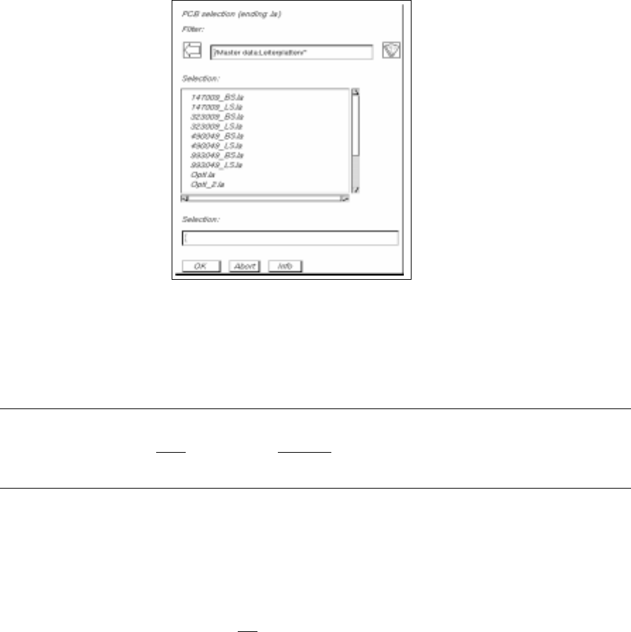
● Select the FILE --> Save as menu item.
The FSB containing the file selection of all already-defined PCBs opens.
User Manual Line Computer UNIX 4 Data Management
Software Version 501.xx 01/99 Issue 4.6 CAD Import
4 - 43
● Enter the name "xxx.la" via the keyboard and confirm with OK.
The file is saved under the name entered.
Above the display area adjacent to "Converted structure", the path and the name of the converted
structure are now displayed.
NOTE
The name may comprise max.
20 characters, including the suffix ".la". Some characters must not
be used when assigning the name; more details are contained in chapt. 2, section 2.3.
- Convert
This menu item is used to start the conversion using the specified filter.
- Discard
Any already-converted data that have not
been saved yet are discarded.
4 Data Management User Manual Line Computer UNIX
4.6 CAD Import Software Version 501.xx 01/99 Issue
4 - 44
4.6.2.2 SERVICES Menu
The SERVICES menu contains the following menu items:
- New filter
This menu item is used to define a new filter.
● Load CAD file (see section 4.6.2).
● Select the SERVICES --> New filter menu item.
The "PCB filter dialog" window opens (see Fig. 4.6.4).
CAD Import is now in the
Filter editing mode
.
The further procedure to be followed is described in section 4.6.3.
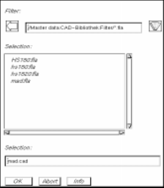
● Click on the filter selection button in the "PCB filter dialog" window.
The FSB containing the contents of the "Master data:CAD-Bibliothek:Filter" directory opens.
● Enter the name of the new filter "xx.fla" and confirm with OK (or RETURN).
The FSB closes and the name entered is transferred to the "Filter" field.
● Define the desired filter-specific data (see section 4.6.3.1) and allocate the CAD data to the posi-
tion fields (see section 4.6.3.2).
● Click on OK for the filter data to be accepted (saved). The filter dialog window closes.
- Modify filter
This menu item is used to change the data of an existing filter.
● Load CAD file (see section 4.6.2).
● Select the SERVICES --> Modify filter menu item.
The "PCB filter dialog" window opens containing the filter selected from the main window. CAD
Import is now in the
Filter editing mode
.
● Perform the required changes.
● Click on OK for the modified filter data to be accepted (saved).
A dialog box containing a verification query as to whether the "xx.fla" file is to be overwritten is dis-
played.
● Click on OK in the dialog box if the filter is to be saved under the same name (or click on Cancel
and subsequently save the filter under a new name as described above).
The dialog box and the filter dialog window are closed.