00191413-01.pdf - 第227页
User Manual Line Computer UNIX 6 Product / Package Form Software Version 501.xx 01/99 Issue 6.1 Package Form Editor 6 - 49 Proced ure: ● Select t he data of the de sired b all mo del from the "M odels" s electi…

6 Product / Package Form User Manual Line Computer UNIX
6.1 Package Form Editor Software Version 501.xx 01/99 Issue
6 - 48
Changing a Grid Group
●
Click on the grid group in the view area of the main window.
The selected grid group is surrounded by a frame.
●
Select the grid group once
more
by double-clicking.
The window for editing the grid group is opened (see Fig. 6.1.25).
●
Click on the editing field containing the value to be changed (position cursor in front of the value).
●
Delete the value using the DELETE key and enter new value.
NOTE
If the RETURN key is pressed after a value has been changed, the graphical display of the
package form is automatically updated in the view area.
●
After all desired changes have been made, click on
OK
.
If the entered values are correct, the window is closed.
The grid group is displayed in the view area with the modified dimensions.
Removing Balls From a Grid Group
To identify any possible absence of given "balls" within a grid, the balls concerned can be clicked on
in the "Grid group description" window.
Procedure:
●
Click on each of the balls you want to remove using the right mouse button. The selected balls
are thereafter displayed in reverse video. By clicking once more with the right
mouse button their
state can be reversed again.
Allocating a New Ball Model to the Current Grid Group
If several ball models were already defined, the model data are displayed in the "Models" selection field
(see Fig. 6.1.25) and can thus be allocated to the current grid group.
The entry for a ball model comprises the following data:
Num
= Number of the ball model
Typ
= Type of the ball model (El. connection or Centering fiducial)
Rad
= Radius of the ball model
Tol
= Radius tolerance of the ball model
User Manual Line Computer UNIX 6 Product / Package Form
Software Version 501.xx 01/99 Issue 6.1 Package Form Editor
6 - 49
Procedure:
●
Select the data of the desired ball model from the "Models" selection field.
●
Click on
OK
.
The window is closed. The grid group is displayed in the view area with the dimensions of the
selected ball model.
Defining a New Ball Model
●
From the view area select a ball of the newly created grid group by double-clicking.
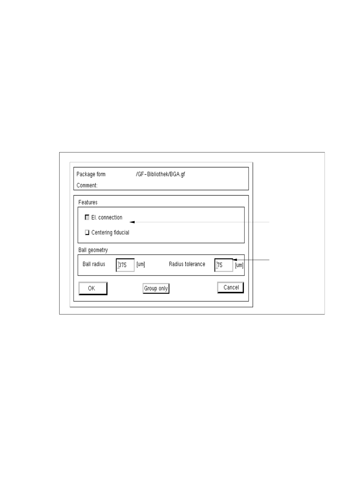
The window for editing the model data is opened (see Fig. 6.1.26).
Fig. 6.1.26 Window "Model Description" (with values for the ball geometry already entered)
Procedure for Editing the BGA Ball Model Data:
●
Click on the individual editing fields and enter the values.
●
After the data have been entered, click on
OK
to confirm your entries.
If the entered values are correct, the window for the model description is closed. The grid group
with the defined balls is displayed in the view area (see Fig. 6.1.3).
settin
g
area
editin
g
fields

6 Product / Package Form User Manual Line Computer UNIX
6.1 Package Form Editor Software Version 501.xx 01/99 Issue
6 - 50
NOTE
If invalid values were entered, a dialog box containing a corresponding error message is displayed
(see page 6 - 15). The fields containing the invalid values are surrounded by a red frame. The dialog
box must first be acknowledged by clicking on
OK
. Thereafter, the entries can be corrected and con-
firmed by clicking on "OK".
Setting the Features of the Balls Within a Grid Group
The characteristic features of the balls of a selected grid group can be defined with the aid of the buttons
"El. connection" and "Centering fiducial" in the setting area of the "Model description" window (see Fig. 6.1.26).
-
El. connection
If this button is activated, all balls of a selected grid group can be defined to be electrically conductive.
NOTE
By default, the button "El. connection" is automatically activated when the "Model description" window
is opened. This means that all balls within the grid groups are designated as an "El. connection", i.e.
they are electrically conductive. This setting can subsequently be changed for each individual grid
group.
Procedure:
●
Select any ball from the grid group whose balls are to be defined as "electrically not conductive",
by double-clicking.
●
Deactivate the
El. connection
button in the setting area.
Now, the balls of the selected grid group are not conductive.
-
Centering fiducial
The selected grid group can be defined as an alignment structure for the determination of the position
of the component at the nozzle.
(This function is not implemented in the present software version).
Changing a Ball Model
NOTE
The procedure for changing the data of a defined ball model is the same as for changing a pin model
The relevant procedure is described on page 6 - 44.