00191413-01.pdf - 第314页
10 Production Tools / Restrictions User Manual Line Computer UNIX 10.1 Restriction Editor Software Version 501.xx 01/99 Issue 10 - 8 - (Allocate) When this icon is acti ve, the ed itor is in the allocation mode. The cu r…
User Manual Line Computer UNIX 10 Production Tools / Restrictions
Software Version 501.xx 01/99 Issue 10.1 Restriction Editor
10 - 7
NOTE
If bindings, exclusions or allocations have already been defined for the selected component, these
are displayed in the selection field "Restrictions/Allocations".
Depending on the currently set mode, the locations for which bindings and exclusions have been defi-
ned, are highlighted in color (see chart, page 10 - 4).
10.1.3.3 Command Area
The commands are symbolized by icons. They determine the mode (selection, allocation, binding, exclusion or
deletion mode) in which the Restriction Editor is to operate.
NOTE
Upon opening, the Restriction Editor is initially in the selection mode.
- (Select)
When this icon is active (displayed in reverse video with the arrow pointing from the lower left to the
upper right), the editor is in the selection mode. It is possible to select machine types or individual ele-
ments from the display area, or feeding units from the selection fields, by clicking the left mouse
button.
● Click on icon in the command area.
(The arrow in the icon now points to the upper right).
● Click on the location (feeder part or entire machine) in the display area (see Fig. 10.1.1). The
selected element is highlighted in green.
In the selection field "Placeable feeders" all feeders, waffle-pack trays and customer-specific
types are displayed that can be set up and which were defined for the selected element.
NOTE
Double-clicking on an entry in the "Placeable feeders" selection field causes the sub-editor for editing
the feeder or waffle-pack tray data to be opened (see section 9.1, Figs. 9.1.3 and 9.1.4). The sub-
editor allows existing feeder or waffle-pack tray data to be modified or new customer-specific types to
be created. The procedure to be followed is described in detail in chapt. 9 "Feeder Editor", section
9.1.4.
The modified data or newly created customer-specific types are only
valid for the current production
job. They remain valid for as long as the lot file exists.
10 Production Tools / Restrictions User Manual Line Computer UNIX
10.1 Restriction Editor Software Version 501.xx 01/99 Issue
10 - 8
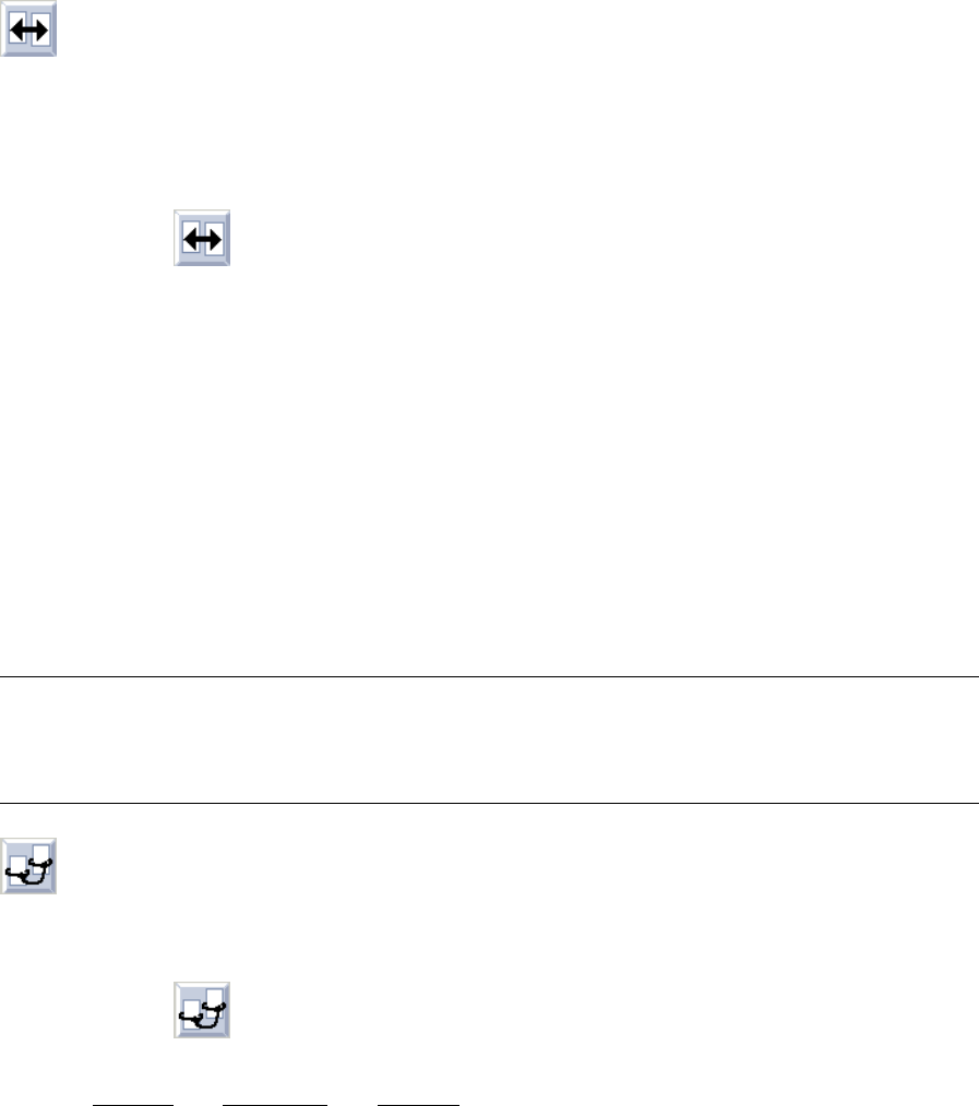
- (Allocate)
When this icon is active, the editor is in the allocation mode. The current component can be allocated
to alternative feeders or alternative waffle-pack trays. They temporarily replace for this current produc-
tion job the default feeding units that are entered for the current component (package form) in the ".ri"-
file (see chapt. 9).
● Click on icon in the command area.
● Click on the location (feeder part or entire machine) in the display area where the alternative
feeder or waffle-pack tray with the current component is to be set up. The selected element is
now highlighted in green.
● Select feeder or waffle-pack tray from the "Placeable feeders" selection field.
The name of the allocated feeder or waffle-pack tray is displayed in the selection field
"Restrictions/Allocations", preceded by the letter "A".
Behind the name the machine type is entered on which the current component is to be set up.
If a particular feeder part is selected, also the side is entered on which the feeder part is located,
with the letter "L" designating the left side and "R" the right side.
Example: Z S_G_8_EL S_SIP_80S L
Feeder Machine type Side
(SIPLACE 80S) ("left" as seen in the direction of travel)
NOTE
Double-clicking on an entry in the selection field "Placeable feeders" causes the window for
editing the feeder or waffle-pack tray data to be opened (see chapt. 9, Figs. 9.1.3 and 9.1.4).
- (Bind)
When this icon is active, the editor is in the mode which allows bindings for the current component to
be defined.
● Click on icon in the command area.
Defining bindings
to a feeder part or a machine:
● Click on the location (feeder part or entire machine) in the display area on which the current com-
ponent must be set up. All locations for which bindings were already defined, are now highlighted
in yellow. In addition, the window for the definition of bindings is opened (see Fig. 10.1.2).
User Manual Line Computer UNIX 10 Production Tools / Restrictions
Software Version 501.xx 01/99 Issue 10.1 Restriction Editor
10 - 9
Defining bindings
to the complete line:
● Click on arrow below the display of the stations (see Fig. 10.1.1).
The window for the definition of bindings is opened (see Fig. 10.1.2).
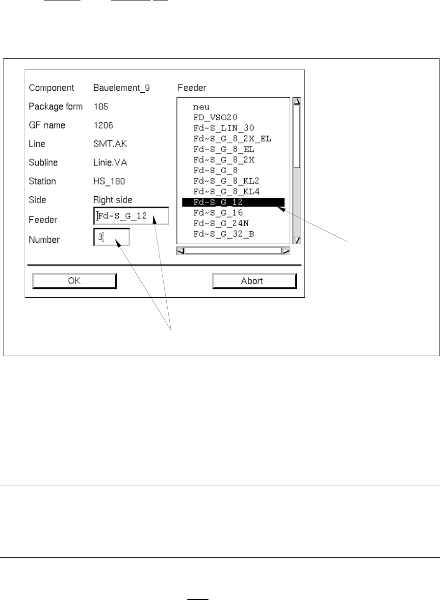
Fig. 10.1.2 Window for the Definition of Bindings
Meaning of the editing fields
- Feeder
Name of the particular feeder or waffle-pack tray by means of which the current component must be
set up at the selected location.
NOTE
Any entry in the editing field "Feeder" is not required.
If no entry is made the default or alternative feeding unit (feeder or waffle-pack tray) specified for the
component and the machine is automatically defined.
- Number
Indicates how often the current component must
be set up at the selected location. As default value a
"1" is entered.
selection field
"Feeder"
editing fields