00191413-01.pdf - 第210页
6 Product / Package Form User Manu al Line Computer UNIX 6.1 Package Form Editor Software Version 501.xx 01/99 Issue 6 - 32 - Adhesive pattern In this f ield the n umber of t he adhe sive pat tern is entered th at has be…
User Manual Line Computer UNIX 6 Product / Package Form
Software Version 501.xx 01/99 Issue 6.1 Package Form Editor
6 - 31
6.1.2.11 Package Form Editor Editing Fields - "Handling data" Screen
Editing field "Handling values"
-
Placing force
Here, as a preset value for the force, a value between 1 and 10
is to be entered, which is then converted into the actual place-
ment force (see Table below).
The setting of the force that is used to place the nozzle on the
component and the component on the board depends on the
following parameters:
Material of the component package
Component size
Composition (consistency) of the adhesive or solder paste
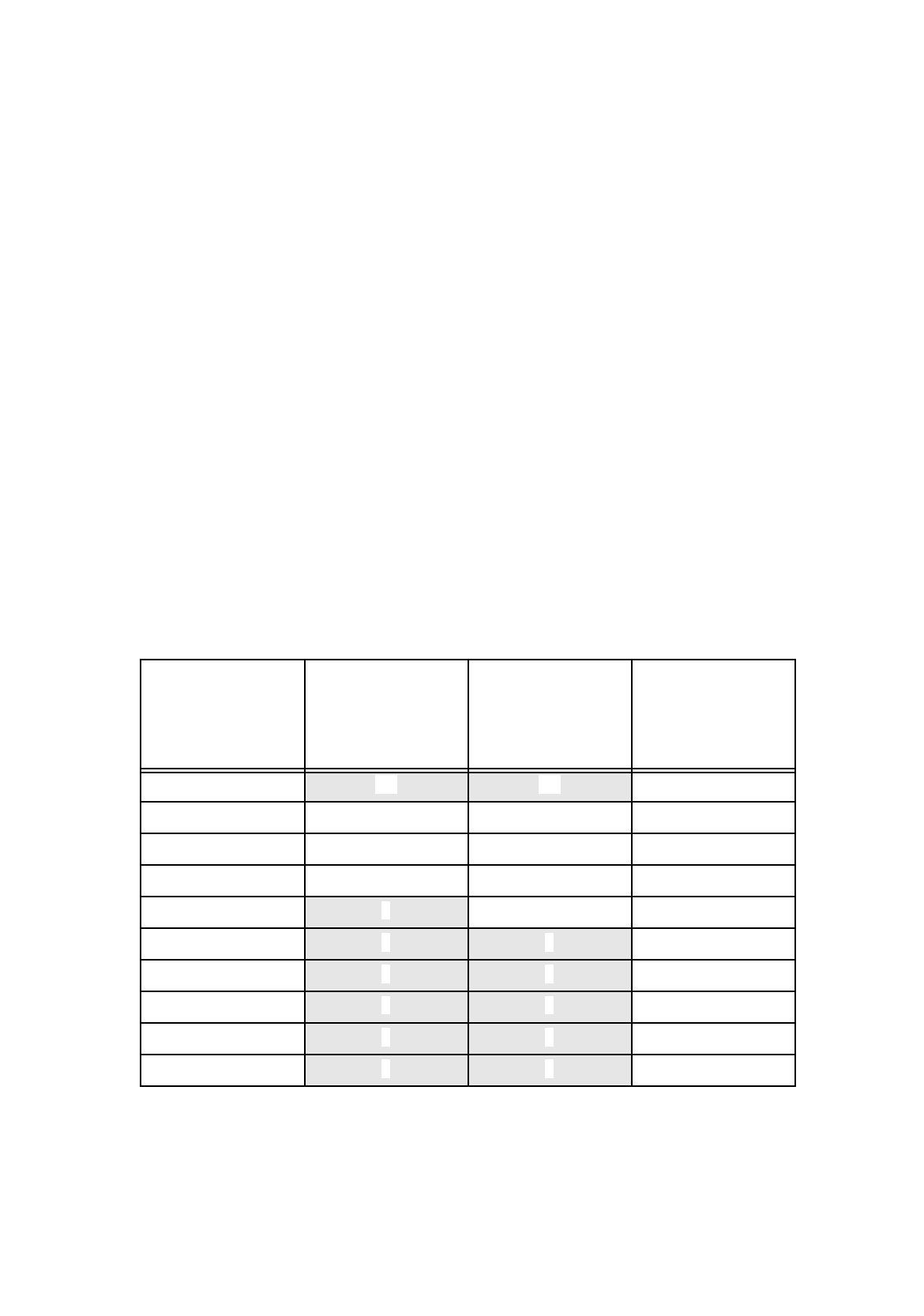
The Table below shows the conversion of the value entered (force presetting) into the value of actual
placement force appropriate for the respective placement head type and the nozzles used.
If the preset value lies, however, below or above the acceptable force setting range, the minimum or
maximum placement force, respectively, will be used for the head type in question (see the shaded
cells).
Value entered
[
N
]
(force presetting)
Actual placement
force
[
N
]
for
revolver head
with 3xx or 6xx type
nozzles
Actual placement
force
[
N
]
for
revolver head
with 7xx or 8xx type
nozzles
Actual placement
force
[
N
]
for
IC-head with 4xx
type nozzle
1 2,4 2,4 1,3
2 2,4 2,4 2
3 3 3 3
4 4 4 4
5 4 5 5
6 4 5 6
7 4 5 7
8 4 5 8
9 4 5 9
10 4 5 10
Tab. 6.1 - 1 Placement Forces

6 Product / Package Form User Manual Line Computer UNIX
6.1 Package Form Editor Software Version 501.xx 01/99 Issue
6 - 32
-
Adhesive pattern
In this field the number of the adhesive pattern is entered that has been
defined for the current package form (see chapt. 7).
-
Dispense setting
In this field a number from 1 to 10 is entered indicating the volume to be
dispensed. The number denotes the quantity of adhesive preset at the
adhesive metering unit for the corresponding adhesive volume setting.
The lowest setting (1) corresponds to the smallest adhesive quantity
dispensed.
NOTE
In the fields "Placing force" and "Dispense setting" numerals must
be entered.
If no number is entered in the field "Adhesive pattern" a default value of "1" automatically applies
to the adhesive pattern, i.e. the adhesive dot is applied centrically with respect to the placement
position.
Procedure to be followed for editing:
●
Click on editing field, enter appropriate number and confirm the entry by pressing the
RETURN key.
NOTE
If invalid numbers (e.g. number too small or too high for the placing force) or characters and
letters have been entered, the fields containing the invalid values are surrounded by a red frame and
must be corrected.
User Manual Line Computer UNIX 6 Product / Package Form
Software Version 501.xx 01/99 Issue 6.1 Package Form Editor
6 - 33
6.1.3 Package Form Definition
6.1.3.1 Definition of the Component’s Coordinate System
NOTE
For the description of a component’s package form, the dimensions should, as a rule, be taken from the corre-
sponding data sheet. Please note, that the description always refers to a component as seen from above.
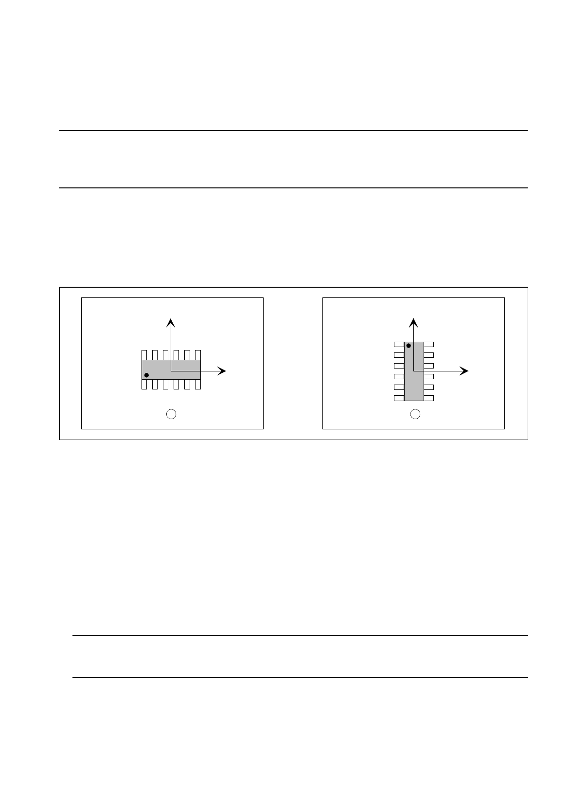
The component is displayed in its 0°-description in the view area of the Package Form Editor. Here, the origin
of the coordinate system is always located in the center of the view area. From there, the X-axis points to the
right, the Y-axis points upward. It is also possible to describe a component both in horizontal and in upright
position (see Fig. 6.1.12). As a rule, the center of the component coincides with the zero point of the coordinate
system.
Fig. 6.1.12 0°-Description in the Package Form Editor
Legend pertaining to Fig. 6.1.12:
➀
Correct (display in the view area)
➁
Incorrect (display in the view area)
The 0°-description of the standard package form contained in the package form library (GF-Bibliothek) is sub-
ject to certain rules which should also be observed for the creation of customer-specific package forms. It can
thus be ensured that different programmers can work with uniformly defined package forms. In this way it is
possible to determine, for example, the pick-up angle at the station without having to check the 0°-description
in the Package Form Editor.
An incorrect 0°-description may result in pick-up or vision errors at the station.
To avoid such errors, the following rule should be observed:
Rule: The long side of nozzles featuring rectangular suction areas is to be positioned along the
X-axis.
This means that die X-axis of the component points in the direction where the nozzle will make contact with the
long side of its suction area (see Fig. 6.1.13).
Exception: special nozzles with 90°-displacement
Y
X
Y
X
Y
X
1 2