00191413-01.pdf - 第470页
14 Control / Cont rol Modules User Manual Line Computer UNIX 14.3 Station Controll ers Software Version 501.xx 01/99 Issue 14 - 34 14.3.3 Opening the "Station Controller" User Interface Every plac ement stati o…

User Manual Line Computer UNIX 14 Control / Control Modules
Software Version 501.xx 01/99 Issue 14.3 Station Controllers
14 - 33
14.3 Station Controllers
Job Control sends jobs to the station controllers of the required stations.
Each physical station has been assigned a station controller supplying the station with machine data, setup
data and placement data and controlling the processes performed at the stations. The data are transmitted to
the stations by the Data Manager via an IEC bus.
The station controller’s user interface provides the operator with the following information:
- current station data
- job allocation
- logged-on PCBs
14.3.1 Tasks
The station controllers are designed to synchronize the user entries at the Job Control with the processes
performed on the stations so that, at the appropriate instant
- setup changeover is initiated
- and the placement data are loaded.
14.3.2 Features
Jobs (batches) are allocated to the station controller by a job control.
- Several jobs can be allocated to a station controller at once.
Active are: without barcode ---> the first lot
with barcode ---> n-lots of the same setup
- Each station controller is allocated to one physical station.
- The station controller allows the handling of "high-priority" jobs.

14 Control / Control Modules User Manual Line Computer UNIX
14.3 Station Controllers Software Version 501.xx 01/99 Issue
14 - 34
14.3.3 Opening the "Station Controller" User Interface
Every placement station represented in the current line configuration display is provided with an icon labelled
with the "i" symbol (see "Desktop" user interface in chapt. 3, Fig. 3.1.2). Clicking on this symbol causes the
user interface of the respective station controller to be opened.
● Click on the area of the desired station containing the "i" symbol.
The user interface (main window) of the station controller is opened (see Fig. 14.3.1).
The following information on the selected station is provided in this window:
- names of Line and Station
- settings of Barcode and UFO strategies
- lot name, PCB type, number of pieces (PCBs)
- PCB identification number
- setup of station
- current conveyor width setting
- listings of lots and PCBs
NOTE
While the main window of the station controller is open, the data is continuously updated, i.e. all chan-
ges are displayed immediately.
User Manual Line Computer UNIX 14 Control / Control Modules
Software Version 501.xx 01/99 Issue 14.3 Station Controllers
14 - 35
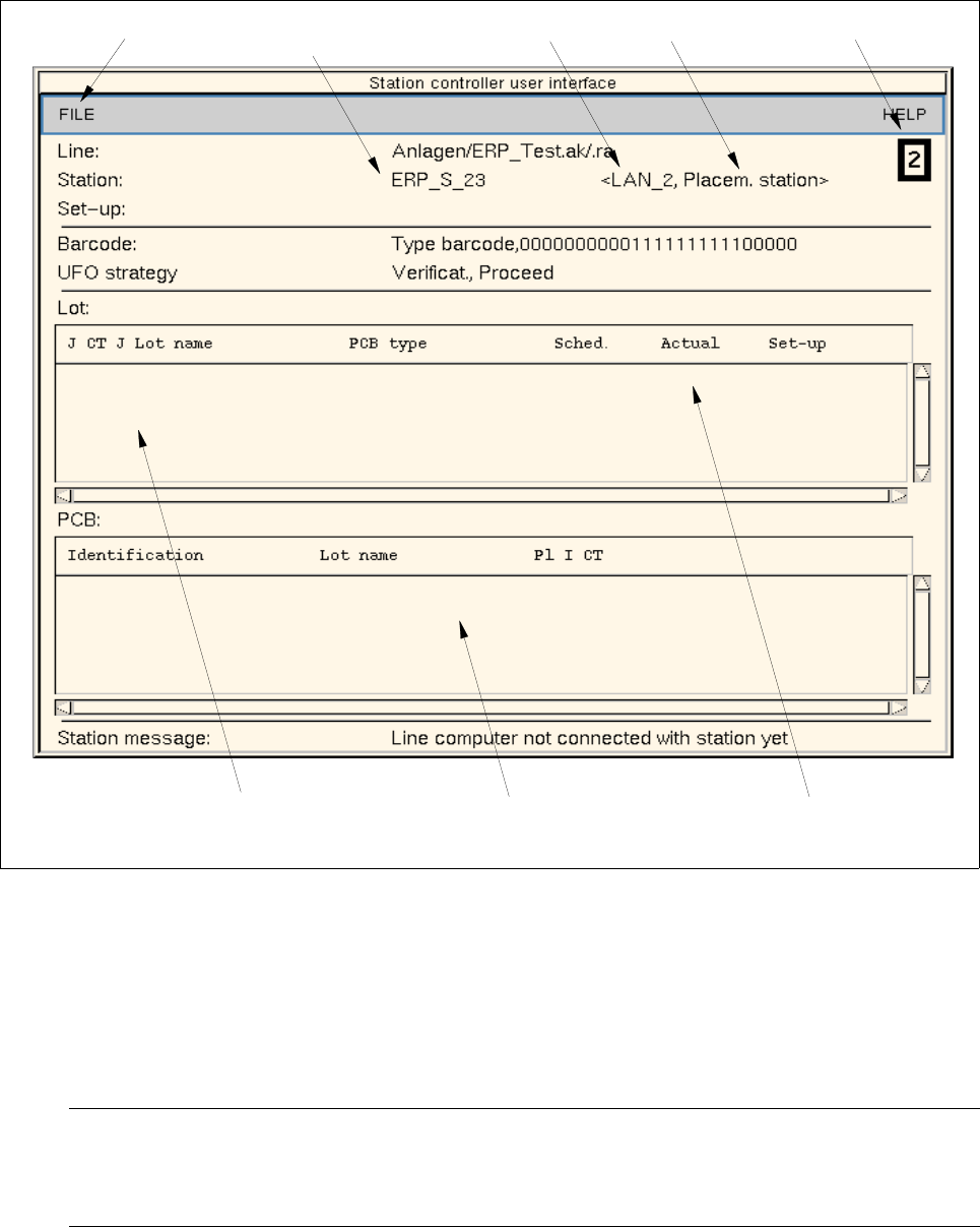
14.3.4 Main Display Window of the Station controller
The various elements of the main display window and their tasks are described in the following.
Fig. 14.3.1 Main Window "Station Controller"
The main display window is subdivided as follows:
- Menu bar
The menu bar contains the menus "FILE" and "HELP".
NOTE
Since the functions and operation of the menus "FILE" and "HELP" are similar to those in other
application programs of the line computer, they described in detail in chapt. 2.
- Display Area
menu bar
listing of the scheduled lots
IEC bus address
logic name
type of station
of station
listing of the currently
processed (scheduled) PCBs
Station number
display area