00191413-01.pdf - 第275页
User Manual Line Computer UNIX 8 Product / PCB Software Version 501.xx 01/99 Issue 8.1 PCB Editor 8 - 37 Menu Bar The menu ba r contai ns the menus "FI LE", "ED IT", "SERV ICES" an d "H…
8 Product / PCB User Manual Line Computer UNIX
8.1 PCB Editor Software Version 501.xx 01/99 Issue
8 - 36
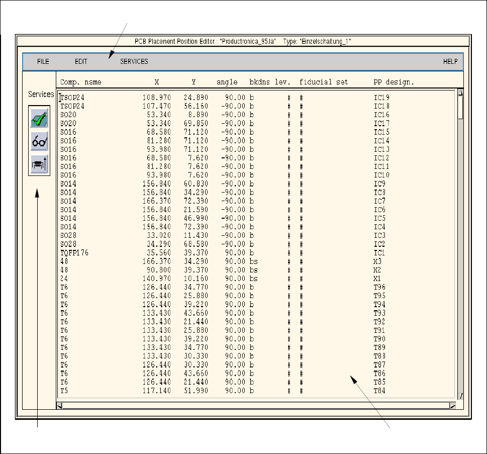
8.1.6 Window of Placement Position Editor
A Placement Position Editor can be opened for every PCB type generated (see description on page 8 - 10).
In the following, the areas of the Placement Position Editor window and their functions are explained.
Fig. 8.1.11 Window "Placement Position Editor"
The window of the Placement Position Editor is subdivided as follows:
- Menu bar
- Display area
- Editing area
- Command area
menu bar
editing area
command area

User Manual Line Computer UNIX 8 Product / PCB
Software Version 501.xx 01/99 Issue 8.1 PCB Editor
8 - 37
Menu Bar
The menu bar contains the menus "FILE", "EDIT", "SERVICES" and "HELP".
The "EDIT" menu is described in detail in section 8.1.6.1 and the "SERVICES" menu is described in section
8.1.6.2.
NOTE
Since the functions and operation of the "FILE" and "HELP" menus are similar to those in other application
programs of the line computer, they are described comprehensively in chapt. 2.
Editing area (see section 8.1.6.3)
For each PCB type selected in the Structure Editor a placement program can be created in the editing area of
the Placement Position Editor window (see Fig. 8.1.11). Such a program contains the positions of the
components to be placed (with reference to the PCB zero point, see Fig. 8.1.3) as well as the fiducial sets that
may be required for component position recognition.
A completed placement program can also be adopted by another PCB type or modified, if required. Moreover,
it is possible to copy only those parts of a placement program that are required for a different PCB type.
Command area (see section 8.1.6.4)
In this area the icons "Check placement position data", "Search/Replace" and "Sort" are located. By means of
these icons the entered placement position data can be reviewed, searched and replaced, or e.g. sorted by the
level numbers, if required.
8 Product / PCB User Manual Line Computer UNIX
8.1 PCB Editor Software Version 501.xx 01/99 Issue
8 - 38
8.1.6.1 EDIT MENU
- Resetting Placement Position data
The entries already existing for the PCB type concerned can be deleted from the editing area.
● Click on EDIT --> Reset placement position.
The editing area is empty, new entries can be made.
NOTE
If the PCB Editor is exited from without activating "Save" (in the Structure Editor), the old data will be
displayed again when the Placement Position Editor is called up.
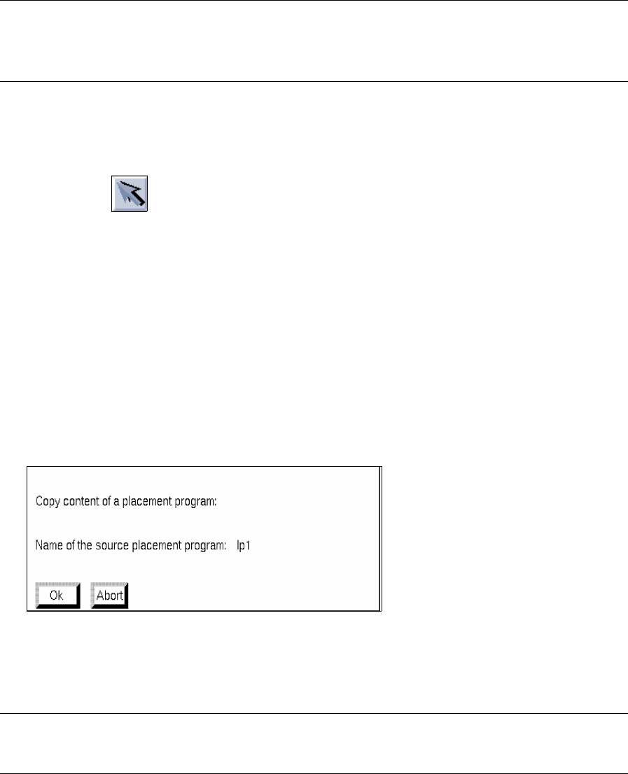
- Loading placement position of an existing PCB type
This function enables a placement program of another PCB type to be loaded into the Placement
Position Editor of the current PCB type.
● Activate icon in the command area of the current Structure Editor.
● Select partial PCB structure (target).
● Click on SERVICES --> Placement Position Editor.
The window of the Placement Position Editor is opened.
● Click on FILE --> Open....
The FSB for the selection of the (source) PCB is opened (see page 8 - 6).
● Select PCB by double-clicking.
The main window of the new Structure Editor is opened.
● Click on the partial PCB structure containing the PP data to be copied (source).
● Activate EDIT --> Load placement position from in the current Placement Position Editor (target).
The following dialog box appears:
● Confirm dialog box with OK .
The loaded placement program is displayed in the window of the Placement Position Editor.
NOTE
If data had already been entered in the editing area, these will be replaced with the copied data.