00191413-01.pdf - 第241页
User Manual Line Computer UNIX 8 Product / PCB Software Version 501.xx 01/99 Issue 8.1 PCB Editor 8 - 3 8.1.1. 3 P CB Struct ure PCBs c an be l inked (a s in a net work) to other PCB s vi a their p artial s tructur es. A…

8 Product / PCB User Manual Line Computer UNIX
8.1 PCB Editor Software Version 501.xx 01/99 Issue
8 - 2
8.1.1 Description of a PCB
8.1.1.1 PCB Data
The PCB data can be categorized into source data and process-specific data.
- The source data contain the description of a PCB.
- The process-specific data are generated from the source data for a given system, i.e. for a given
setup selected by the user.
8.1.1.2 PCB Source Data
- PCB Type
The PCB type contains the basic description of a PCB type consisting of data for clusters, fiducials,
component positions as well as cross-references given to other descriptions of partial PCB structures.
Sample file name of PCB type "A": A.lb
- Partial PCB Structure
This partial PCB structure contains the PCB type description as well as its coordinate data
(see Fig. 8.1.2).
Sample file name of partial PCB structure "A": A.lp
- Overall PCB Structure
When the generated process-specific data are added to the source data, then all data required for
assembling the PCB are available.
Sample file name of overall PCB structure "A": A.la
User Manual Line Computer UNIX 8 Product / PCB
Software Version 501.xx 01/99 Issue 8.1 PCB Editor
8 - 3
8.1.1.3 PCB Structure
PCBs can be linked (as in a network) to other PCBs via their partial structures. A PCB to be assembled is loaded
into the PCB Editor by entering the name (name.la) of the overall PCB structure.
In the main display window of the PCB Editor, the Structure Editor, the structure of said PCB loaded is displayed
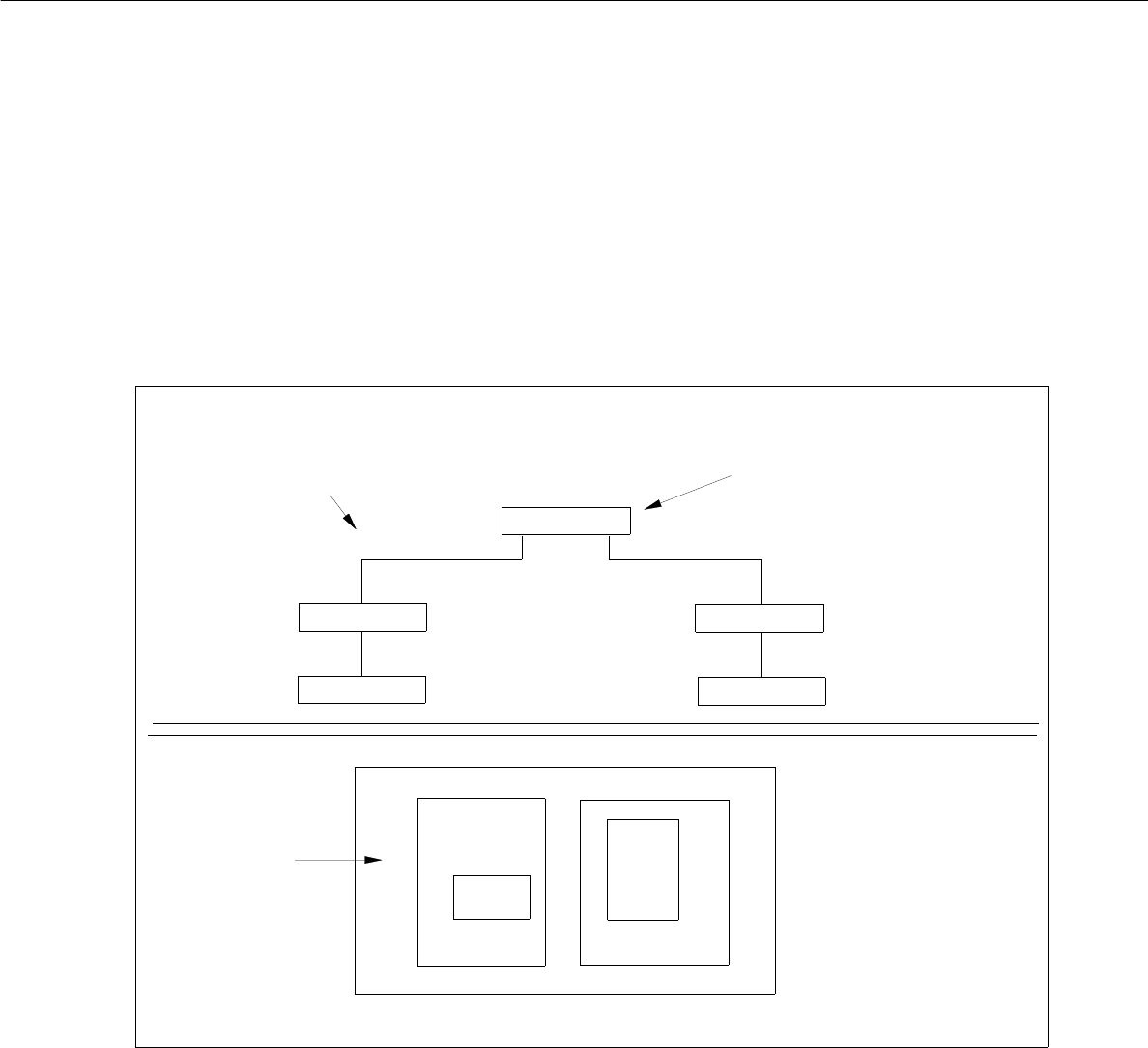
and can be changed. The example in Fig. 8.1.1 shows such a structure and the associated PCB layout.
Fig. 8.1.1 PCB Structure (sample PCB "A")
PCB B
PCB C
LP E
LP D
overall PCB structure
(displayed in the display area)
associated
PCB layout
uppermost partial structure
in the overall PCB structure
PCB B
PCB C
PCB A
PCB
PCB D
PCB D
PCB E
PCB A
PCB B
PCB C
8 Product / PCB User Manual Line Computer UNIX
8.1 PCB Editor Software Version 501.xx 01/99 Issue
8 - 4
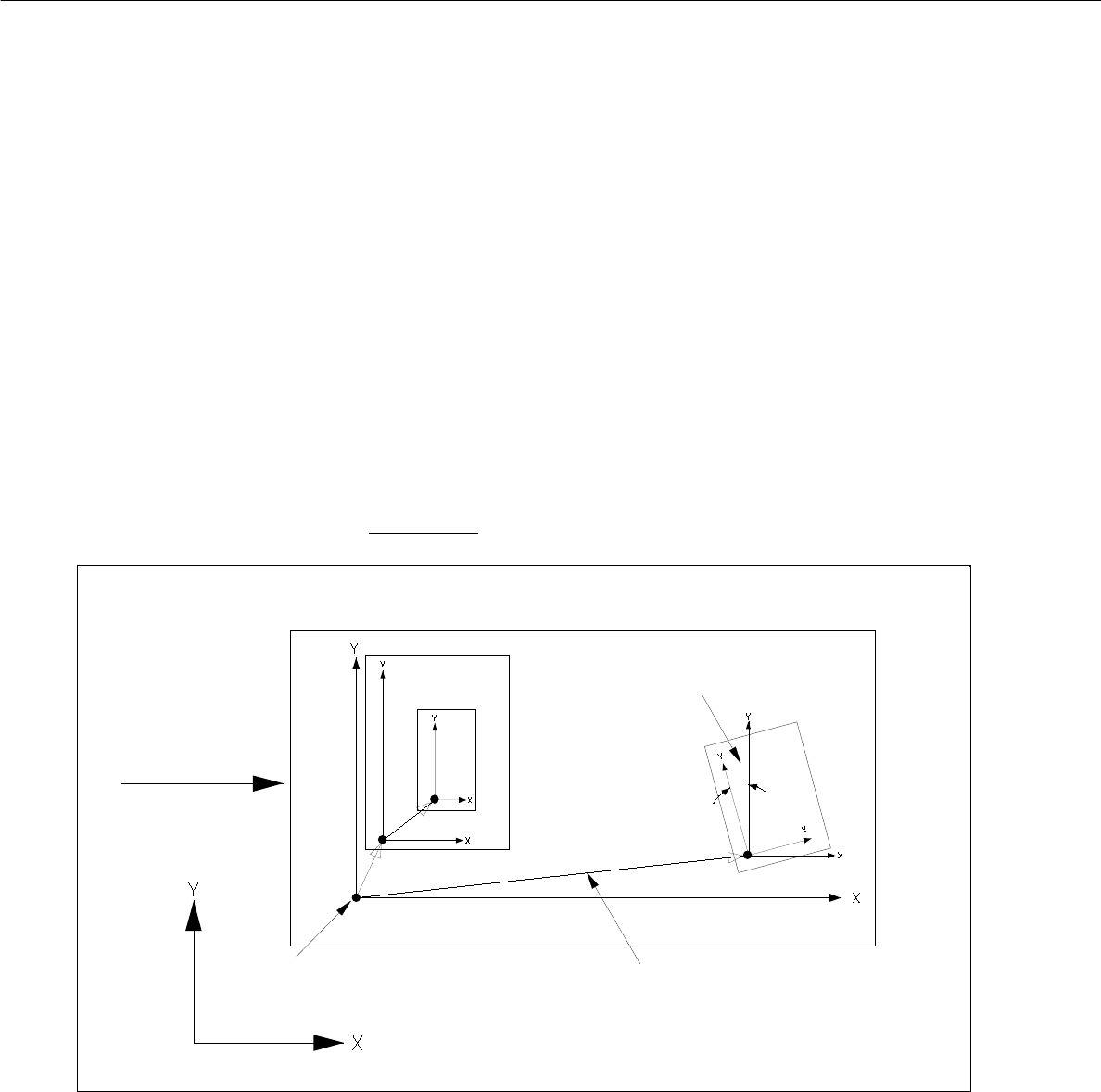
8.1.1.4 PCB Coordinate System
- Each PCB is structured hierarchically. Each structural element (PCB type) is assigned its own
coordinate system. It runs parallel to the axes of the outer edges of the structural element.
- The plane of these coordinate systems is displaced and turned. The plane of the coordinate systems of the
individual structure elements (PCB types) is displaced and rotated.
In each case they are linked to each other by a vector (see Fig. 8.1.2).
The rotational position of the coordinate systems with respect to one another is specified by an angle.
- The outer coordinate system of the entire PCB lies parallel to the axes of the machine’s coordinate system.
- The angle between the machine's coordinate system and the PCB coordinate system can be 0°, 90°, 180°
or 270°.
- The angle between coordinate systems of further partial PCB structures can be chosen as desired. It is
specified in 1/100°.
- The rotational angle is specified anticlockwise (see Fig. 8.1.2). This applies to all angular dimensions!
Fig. 8.1.2 Example "PCB Coordinate System" (PCB position in machine = 0° )"
- The vectors for placement positions, fiducials and ink spots originate in the zero point of the individual PCB
type.
- The vectors for fiducials of the placement positions originate at the placement position.
PCB zero point
machine’s coordinate system
direction of
vectors
rotational angle
PCB transport